


















Обзор
PM240‑2 Power Modules – 0.55 kW to 250 kW, IP20 degree of protection
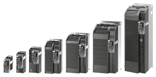
PM240‑2 Power Modules, frame sizes FSA to FSG, with CU310‑2 PN Control Unit and BOP20 Basic Operator Panel
The PM240-2 Power Modules are based on a hardware platform, which permits an increase in power density.
Furthermore, the PM240-2 Power Module is also suitable for use in safety-oriented applications. In conjunction with a fail-safe Control Unit, the drive can be turned into a Safety Integrated Drive.
The PM240‑2 Power Modules in frame sizes FSA to FSF are available both with and without an integrated line filter class A of compact design for 200 V, 400 V and 690 V line voltages (except PM240‑2 frame sizes FSD to FSF: 200 V). The PM240‑2 Power Modules in frame size FSG are available with an integrated line filter Category C3 of compact design for 400 V and 690 V line voltages, also with integrated line filter Category C2 for a line voltage of 400 V. In addition, a DC link reactor is integrated in the PM240‑2 Power Modules, frame sizes FSD to FSG, and therefore no line reactor is required.
The PM240-2 Power Modules with integrated line filter class A are suitable for connection to TN supply systems. Power Modules without integrated line filter can be connected to grounded TN/TT systems and non-grounded IT systems.
The PM240‑2 Power Module has an integrated braking chopper. In generating mode, the excess energy of the DC link can be dissipated by means of an optional braking resistor.
The permissible cable lengths between converter and motor are limited. Longer cables can be used if output reactors are connected.
Shield plates and shield connection kits are available for use in wiring the Power Modules to ensure they comply with EMC guidelines.
For more information, see shield connection kits for blocksize format.
Additional options
Further selected accessories are available from "Siemens Product Partner for Drives Options":
Интеграция
All Power Modules have the following connections and interfaces:
- PM‑IF interface to connect the Power Module to the Control Unit. The Power Module also supplies power to the Control Unit using an integrated power supply
- Motor connection using screw terminals or screw studs
- 2 PE/protective conductor connections
- Shield connection plate
PM240-2 Power Modules come together with the CU310‑2 and CU320‑2 Control Units, which are responsible for communication functions as well as open-loop control and closed-loop control functions, to form powerful SINAMICS S120 drives.
PM240‑2 Power Modules in the blocksize format communicate via the PM-IF interface with
- the CU310‑2 Control Unit
- the SIMOTION D410-2 DP Control Unit
- CUA31 or CUA32 Control Unit Adapter
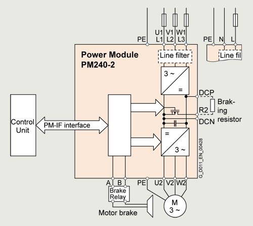
Connection example for PM240‑2 Power Modules, frame sizes FSA to FSC, with or without integrated line filter
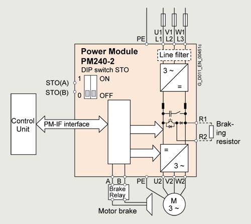
Connection example for PM240‑2 Power Modules, frame sizes FSD to FSG, with or without integrated line filter
With a CUA31/CUA32 Control Unit Adapter snapped on, the PM240‑2 Power Module communicates via a DRIVE‑CLiQ connection with
- a CU320‑2 Control Unit
- a SINUMERIK 840D sl
- a SINUMERIK ONE
- a SINUMERIK MC
- a SIMOTION D4x5‑2 Control Unit
Power and DC link components that are optionally available depending on the Power Module used
The following line-side components, DC link components and load-side power components are optionally available in the appropriate frames sizes for the Power Modules:
Frame size |
|||||||
|---|---|---|---|---|---|---|---|
FSA |
FSB |
FSC |
FSD |
FSE |
FSF |
FSG |
|
PM240-2 Power Module with integrated braking chopper | |||||||
|
✓ |
✓ |
✓ |
✓ 1) |
✓ 1) |
✓ 1) |
– |
|
✓ |
✓ |
✓ |
✓ |
✓ |
✓ |
✓ |
|
– |
– |
– |
✓ |
✓ |
✓ |
✓ |
Line-side components | |||||||
Line filter class A |
F |
F |
F |
F 1) |
F 1) |
F 1) |
– |
Line filter class B (only for 400 V versions) |
U |
U |
U |
– |
– |
– |
– |
Line filters of Category C2 or C3 (for 400 V versions frame size FSG) |
– |
– |
– |
– |
– |
– |
I 2) |
Line Filters of Category C3 (for 690 V versions frame size FSG) |
– |
– |
– |
– |
– |
– |
I 2) |
Line Harmonics Filters (only for 400‑V variants, frame sizes FSD to FSG) |
– |
– |
– |
S |
S |
S |
S |
Line reactors (only for 3‑AC versions 3)) |
S 4) |
S 4) |
S 4) |
I |
I |
I |
I |
DC link components | |||||||
Braking resistor |
S |
S |
S |
S |
S |
S |
S |
Load-side power components | |||||||
Output reactor |
S |
S |
S |
S |
S |
S |
S |
Sine-wave filters (only for 400‑V variants) |
S |
S |
S |
S |
S |
S |
S |
dv/dt filters plus VPL (only for 400‑V variants) |
– |
– |
– |
S |
S |
S |
– |
dv/dt filters plus VPL (only for 690‑V variants 5)) |
– |
– |
– |
S |
S |
S |
S |
U = Base component
S = Lateral mounting
I = Integrated
F = Power Modules available with and without integrated filter class A
– = Not possible
1) The 200 V versions of the PM240‑2 Power Modules, frame sizes FSD to FSF, are only available without integrated line filter.
2) PM240‑2 Power Modules in frame size FSG, equipped with an integrated Category C3 line filter, can be operated in the following power supply systems (up to 600 V):
- TN systems with a grounded line conductor
- TT systems without a grounded neutral point
- IT systems, provided the functional grounding screw is removed
Note: Removing the functional grounding screw is required for operation in IT systems. However, this action degrades the EMC performance, and the device no longer complies with Category C3 requirements.
3) With the appropriate wiring, the line reactors for 200 V 3 AC can be used for the 200 V versions for 200 V 1 AC. More information can be found on the internet at:
4) For frame sizes FSA to FSC, for lines with uk < 1%, it is recommended that you use a line reactor or the next more powerful Power Module. More information can be found on the internet at:
5) The 690 V versions of the PM240‑2 Power Modules require motors with a suitable isolating system for 690 V converter operation (IVIC‑C premium).
General design information
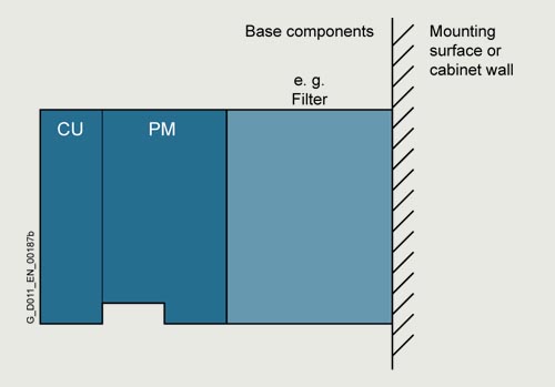
Frequency converter comprising a Power Module (PM), a Control Unit (CU), and base components (side view)
- If at all possible, the line filter should be mounted directly below the frequency converter.
- With lateral mounting, the line-side components have to be mounted on the left side of the frequency converter, and the load-side
components on the right side. - Braking resistors have to be mounted directly on the control cabinet wall due to heating issues.
Recommended installation combinations of the converter and optional power and DC link components
Power Module |
Base |
Lateral mounting |
|
|---|---|---|---|
Frame size |
To the left of the converter |
Right of the converter |
|
FSA and FSB |
Line filters, sine-wave filters |
Line reactor |
Output reactor and/or |
FSC |
Line filters 1), sine-wave filters |
Line reactor |
Output reactor and/or |
FSD and FSE |
– |
Line filters, Line Harmonics Filters |
Output reactor or |
FSF and FSG |
– |
Line filters, Line Harmonics Filters |
Output reactor or |
Технические данные
General technical specifications
Note:
When engineering the complete SINAMICS S120 drive, the system data of the associated Control Units, supplementary system components, DC link components and Sensor Modules must be taken into consideration.
Power Modules |
PM240‑2 |
|---|---|
System operating voltage |
FSA ... FSC: FSD ... FSG: |
Network requirement |
200 V: >25 With RSC >50 it is advisable for FSA to FSC to install a line reactor, or alternatively, to select a Power Module with the next-higher power rating. 400 V: >25 With RSC >100 it is advisable for FSA to FSC to install a line reactor, or alternatively, to select a Power Module with the next-higher power rating. 690 V: No restriction |
Input frequency |
47 ... 63 Hz |
Output frequency |
|
|
0 ... 550 Hz |
|
0 ... 240 Hz |
Pulse frequency |
200 V: 4 kHz 400 V: ≤90 kW: 4 kHz; >90 kW: 2 kHz 690 V: 2 kHz For higher pulse frequencies, see derating data |
Power factor λ |
FSA ... FSC: FSD ... FSG: |
Displacement factor cos φ |
FSA ... FSC: >0.96 FSD ... FSG: 0.98 ... 0.99 |
|
Converter efficiency According to IEC 61800-9-2 |
200 V: >96.2 ... 97.1 % 400 V: >96.0 ... 98.0 % 690 V: >97.3 ... 98.2 % |
|
Efficiency class According to IEC 61800-9-2 |
IE2 |
|
Output voltage, max. In % of input voltage |
95% |
Overload capability |
|
Note: When the overload capability is used, there is no reduction in the rated current IN. |
1.5 × rated current IN (i.e. 150% overload) for 3 s plus 1.1 × rated current IN (i.e. 110% overload) for 57 s within a cycle time of 300 s |
Note: No reduction in base-load current IH for use of overload. |
2 × base-load current IH (i.e. 200 % overload) for 3 s plus 1.5 × base-load current IH (i.e. 150 % overload) for 57 s within a cycle time of 300 s |
For more information on overload capability, see Characteristic Curves section. | |
Possible braking methods |
DC braking Compound braking Dynamic braking with integrated braking chopper |
Degree of protection |
IP20 (standard) |
Operating temperature |
|
|
Frame sizes FSA ... FSC: Frame sizes FSD ... FSG: |
|
Frame sizes FSA ... FSC: Frame sizes FSD ... FSG: |
Relative air humidity |
<95 % RH, condensation not permissible |
Cooling |
200 V, 400 V from 1.5 kW, 690 V: |
Installation altitude |
Up to 1000 m (3281 ft) above sea level without derating, |
Protection functions |
|
|
Short-Circuit Current Rating SCCR according to UL |
200 V: 100 kA 400 V: 100 kA 690 V: 100 kA |
Compliance with standards |
CE, UKCA, cULus, RCM, SEMI F47, RoHS, EAC For frame size FSD ... FSG also: WEEE (Waste Electrical & Electronic Equipment) |
CE marking, according to |
Low-Voltage Directive 2014/35/EU Ecodesign requirements of the EU Directive 2019/1781 EMC Directive 2014/30/EU |
1) Applies to industrial control cabinet installations to NEC article 409 or UL 508A.
Environmental Product Declaration (EPD)
Environmental Product Declarations (EPD) are available as PDFs for this product.
The EPD PDF provides brief and concise information about the ecological properties of a product.
You can find more information on the internet at:
PM240‑2 Power Modules standard variant
Line voltage 200 ... 240 V 1 AC/3 AC |
PM240‑2 Power Modules standard variant |
|||||
|---|---|---|---|---|---|---|
Without integrated line filter |
6SL3210-1PB13-0UL0 |
6SL3210-1PB13-8UL0 |
6SL3210-1PB15-5UL0 |
6SL3210-1PB17-4UL0 |
6SL3210-1PB21-0UL0 |
|
With integrated line filter class A |
6SL3210-1PB13-0AL0 |
6SL3210-1PB13-8AL0 |
6SL3210-1PB15-5AL0 |
6SL3210-1PB17-4AL0 |
6SL3210-1PB21-0AL0 |
|
|
Output current at 50 Hz 230 V 1 AC |
||||||
|
A |
3.2 |
4.2 |
6 |
7.4 |
10.4 |
|
A |
3.3 |
4.3 |
6.1 |
8.2 |
11.5 |
|
A |
2.3 |
3.2 |
4.2 |
6 |
7.4 |
|
A |
4.6 |
6 |
8.3 |
11.1 |
15.6 |
Rated power |
||||||
|
kW (hp) |
0.55 (0.75) |
0.75 (1) |
1.1 (1.5) |
1.5 (2) |
2.2 (3) |
|
kW (hp) |
0.37 (0.5) |
0.55 (0.75) |
0.75 (1) |
1.1 (1.5) |
1.5 (2) |
Rated pulse frequency |
kHz |
4 |
4 |
4 |
4 |
4 |
|
Efficiency η according to IEC 61800-9-2 |
% |
>96.2 |
>96.4 |
>96.7 |
>96.4 |
>96.3 |
|
Power loss 3) according to IEC 61800-9-2 |
kW |
0.037 |
0.046 |
0.061 |
0.082 |
0.118 |
Cooling air requirement |
m3/s (ft3/s) |
0.005 (0.18) |
0.005 (0.18) |
0.0092 (0.32) |
0.0092 (0.32) |
0.0092 (0.32) |
|
Sound pressure level LpA (1 m/3.28 ft) |
dB |
<50 |
<50 |
<62 |
<62 |
<62 |
Input current 4) |
||||||
|
A |
7.5/4.2 |
9.6/5.5 |
13.5/7.8 |
18.1/9.7 |
24/13.6 |
|
A |
6.6/3 |
8.4/4.2 |
11.8/5.5 |
15.8/7.8 |
20.9/9.7 |
|
Line supply connection U1/L1, V1/L2, W1/L3 |
Terminal connector |
Terminal connector |
Terminal connector |
Terminal connector |
Terminal connector |
|
|
mm2 |
1.5 ... 2.5 |
1.5 ... 2.5 |
1.5 ... 6 |
1.5 ... 6 |
1.5 ... 6 |
|
Motor connection U2, V2, W2 |
Terminal connector |
Terminal connector |
Terminal connector |
Terminal connector |
Terminal connector |
|
|
mm2 |
1.5 ... 2.5 |
1.5 ... 2.5 |
1.5 ... 6 |
1.5 ... 6 |
1.5 ... 6 |
PE connection |
Included in terminal connector |
Included in terminal connector |
Included in terminal connector |
Included in terminal connector |
Included in terminal connector |
|
Motor cable length, max. |
||||||
|
m (ft) |
50 (164) |
50 (164) |
50 (164) |
50 (164) |
50 (164) |
|
m (ft) |
100 (328) |
100 (328) |
100 (328) |
100 (328) |
100 (328) |
Degree of protection |
IP20 |
IP20 |
IP20 |
IP20 |
IP20 |
|
Dimensions |
||||||
|
mm (in) |
73 (2.87) |
73 (2.87) |
100 (3.94) |
100 (3.94) |
100 (3.94) |
|
mm (in) |
196 (7.72) |
196 (7.72) |
292 (11.50) |
292 (11.50) |
292 (11.50) |
|
mm (in) |
165 (6.50) |
165 (6.50) |
165 (6.50) |
165 (6.50) |
165 (6.50) |
Frame size |
FSA |
FSA |
FSB |
FSB |
FSB |
|
Weight, approx. |
||||||
|
kg (lb) |
1.4 (3.09) |
1.4 (3.09) |
2.9 (6.39) |
2.9 (6.39) |
2.9 (6.39) |
|
kg (lb) |
1.6 (3.53) |
1.6 (3.53) |
3.1 (6.84) |
3.1 (6.84) |
3.1 (6.84) |
1) The rated output current IN is based on the duty cycle for low overload (LO).
2) The base-load current IH is based on the duty cycle for high overload (HO).
3) Typical values. More information can be found on the internet at
4) The input current depends on the motor load and line impedance. The input currents apply for a load at rated power (based on IN) for a line impedance corresponding to uK = 1 %. The current values are specified on the rating plate of the Power Module.
Line voltage 200 ... 240 V 1 AC/3 AC |
PM240‑2 Power Modules standard variant |
||
|---|---|---|---|
Without integrated line filter |
6SL3210-1PB21-4UL0 |
6SL3210-1PB21-8UL0 |
|
With integrated line filter class A |
6SL3210-1PB21-4AL0 |
6SL3210-1PB21-8AL0 |
|
|
Output current at 50 Hz 230 V 1 AC |
|||
|
A |
13.6 |
17.5 |
|
A |
15 |
19.3 |
|
A |
10.4 |
13.6 |
|
A |
20.8 |
27.2 |
Rated power |
|||
|
kW (hp) |
3 (4) |
4 (5) |
|
kW (hp) |
2.2 (3) |
3 (4) |
Rated pulse frequency |
kHz |
4 |
4 |
|
Efficiency η according to IEC 61800-9-2 |
% |
>96.7 |
>96.7 |
|
Power loss 3) according to IEC 61800-9-2 |
kW |
0.137 |
0.176 |
Cooling air requirement |
m3/s (ft3/s) |
0.0185 (0.65) |
0.0185 (0.65) |
|
Sound pressure level LpA (1 m/3.28 ft) |
dB |
<65 |
<65 |
Input current 4) |
|||
|
A |
35.9/17.7 |
43/22.8 |
|
A |
31.3/13.6 |
37.5/17.7 |
|
Line supply connection U1/L1, V1/L2, W1/L3 |
Terminal connector |
Terminal connector |
|
|
mm2 |
6 ... 16 |
6 ... 16 |
|
Motor connection U2, V2, W2 |
Terminal connector |
Terminal connector |
|
|
mm2 |
6 ... 16 |
6 ... 16 |
PE connection |
Included in terminal connector |
Included in terminal connector |
|
Motor cable length, max. |
|||
|
m (ft) |
50 (164) |
50 (164) |
|
m (ft) |
100 (328) |
100 (328) |
Degree of protection |
IP20 |
IP20 |
|
Dimensions |
|||
|
mm (in) |
140 (5.51) |
140 (5.51) |
|
mm (in) |
355 (13.98) |
355 (13.98) |
|
mm (in) |
165 (6.50) |
165 (6.50) |
Frame size |
FSC |
FSC |
|
Weight, approx. |
|||
|
kg (lb) |
5 (11.0) |
5 (11.0) |
|
kg (lb) |
5.2 (11.5) |
5.2 (11.5) |
1) The rated output current IN is based on the duty cycle for low overload (LO).
2) The base-load current IH is based on the duty cycle for high overload (HO).
3) Typical values. More information can be found on the internet at
4) The input current depends on the motor load and line impedance. The input currents apply for a load at rated power (based on IN) for a line impedance corresponding to uK = 1 %. The current values are specified on the rating plate of the Power Module.
Line voltage 200 ... 240 V 3 AC |
PM240‑2 Power Modules standard variant |
|||||
|---|---|---|---|---|---|---|
Without integrated line filter |
6SL3210-1PC22-2UL0 |
6SL3210-1PC22-8UL0 |
6SL3210-1PC24-2UL0 |
6SL3210-1PC25-4UL0 |
6SL3210-1PC26-8UL0 |
|
With integrated line filter class A |
6SL3210-1PC22-2AL0 |
6SL3210-1PC22-8AL0 |
– |
– |
– |
|
|
Output current at 50 Hz 230 V 3 AC |
||||||
|
A |
22 |
28 |
42 |
54 |
68 |
|
A |
24.2 |
30.8 |
50 |
64 |
81 |
|
A |
17.5 |
22 |
35 |
42 |
54 |
|
A |
35 |
44 |
70 |
84 |
108 |
Rated power |
||||||
|
kW (hp) |
5.5 (7.5) |
7.5 (10) |
11 (15) |
15 (20) |
18.5 (25) |
|
kW (hp) |
4 (5) |
5.5 (7.5) |
7.5 (10) |
11 (15) |
15 (20) |
Rated pulse frequency |
kHz |
4 |
4 |
4 |
4 |
4 |
|
Efficiency η according to IEC 61800-9-2 |
% |
>97.0 |
>96.9 |
>96.7 |
>96.5 |
>96.3 |
|
Power loss 3) according to IEC 61800-9-2 |
kW |
0.217 |
0.282 |
0.463 |
0.626 |
0.843 |
Cooling air requirement |
m3/s (ft3/s) |
0.0185 (0.65) |
0.0185 (0.65) |
0.055 (1.90) |
0.055 (1.90) |
0.055 (1.90) |
|
Sound pressure level LpA (1 m/3.28 ft) |
dB |
<65 |
<65 |
45 ... 65 4) |
45 ... 65 4) |
45 ... 65 4) |
Input current 5) |
||||||
|
A |
28.6 |
36.4 |
40 |
51 |
64 |
|
A |
22.8 |
28.6 |
36 |
43 |
56 |
|
Line supply connection U1/L1, V1/L2, W1/L3 |
Terminal connector |
Terminal connector |
Screw terminals |
Screw terminals |
Screw terminals |
|
|
mm2 |
6 ... 16 |
6 ... 16 |
10 ... 35 |
10 ... 35 |
10 ... 35 |
|
Motor connection U2, V2, W2 |
Terminal connector |
Terminal connector |
Screw terminals |
Screw terminals |
Screw terminals |
|
|
mm2 |
6 ... 16 |
6 ... 16 |
10 ... 35 |
10 ... 35 |
10 ... 35 |
PE connection |
Included in terminal connector |
Included in terminal connector |
Screw terminals |
Screw terminals |
Screw terminals |
|
Motor cable length, max. |
||||||
|
m (ft) |
50 (164) |
50 (164) |
200 (656) |
200 (656) |
200 (656) |
|
m (ft) |
100 (328) |
100 (328) |
300 (984) |
300 (984) |
300 (984) |
Degree of protection |
IP20 |
IP20 |
IP20 |
IP20 |
IP20 |
|
Dimensions |
||||||
|
mm (in) |
140 (5.51) |
140 (5.51) |
200 (7.87) |
200 (7.87) |
200 (7.87) |
|
mm (in) |
355 (13.98) |
355 (13.98) |
472 (18.58) |
472 (18.58) |
472 (18.58) |
|
mm (in) |
165 (6.50) |
165 (6.50) |
237 (9.33) |
237 (9.33) |
237 (9.33) |
Frame size |
FSC |
FSC |
FSD |
FSD |
FSD |
|
Weight, approx. |
||||||
|
kg (lb) |
5 (11.0) |
5 (11.0) |
17 (37.5) |
17 (37.5) |
17 (37.5) |
|
kg (lb) |
5.2 (11.5) |
5.2 (11.5) |
– |
– |
– |
1) The rated output current IN is based on the duty cycle for low overload (LO).
2) The base-load current IH is based on the duty cycle for high overload (HO).
3) Typical values. More information can be found on the internet at
4) Values dependent on ambient temperature and utilization.
5) The input current depends on the motor load and line impedance. The input currents apply for a load at rated power (based on IN) for a line impedance corresponding to uK = 1 %. The current values are specified on the rating plate of the Power Module.
Line voltage 200 ... 240 V 3 AC |
PM240‑2 Power Modules standard variant |
|||||
|---|---|---|---|---|---|---|
Without integrated line filter |
6SL3210-1PC28-0UL0 |
6SL3210-1PC31-1UL0 |
6SL3210-1PC31-3UL0 |
6SL3210-1PC31-6UL0 |
6SL3210-1PC31-8UL0 |
|
With integrated line filter class A |
– |
– |
– |
– |
– |
|
|
Output current at 50 Hz 230 V 3 AC |
||||||
|
A |
80 |
104 |
130 |
154 |
178 |
|
A |
96 |
124 |
156 |
184 |
213 |
|
A |
68 |
80 |
104 |
130 |
154 |
|
A |
136 |
160 |
208 |
260 |
308 |
Rated power |
||||||
|
kW (hp) |
22 (30) |
30 (40) |
37 (50) |
45 (60) |
55 (75) |
|
kW (hp) |
18.5 (25) |
22 (30) |
30 (40) |
37 (50) |
45 (60) |
Rated pulse frequency |
kHz |
4 |
4 |
4 |
4 |
4 |
|
Efficiency η according to IEC 61800-9-2 |
% |
>96.5 |
>96.2 |
>96.7 |
>96.5 |
>96.4 |
|
Power loss 3) according to IEC 61800-9-2 |
kW |
0.937 |
1.31 |
1.45 |
1.81 |
2.20 |
Cooling air requirement |
m3/s (ft3/s) |
0.083 (2.90) |
0.083 (2.90) |
0.153 (5.40) |
0.153 (5.40) |
0.153 (5.40) |
|
Sound pressure level LpA (1 m/3.28 ft) |
dB |
44 ... 62 4) |
44 ... 62 4) |
56 ... 68 4) |
56 ... 68 4) |
56 ... 68 4) |
Input current 5) |
||||||
|
A |
76 |
98 |
126 |
149 |
172 |
|
A |
71 |
83 |
110 |
138 |
164 |
|
Line supply connection U1/L1, V1/L2, W1/L3 |
Screw terminals |
Screw terminals |
M10 screw stud |
M10 screw stud |
M10 screw stud |
|
|
mm2 |
25 ... 70 |
25 ... 70 |
35 ... 2 × 120 |
35 ... 2 × 120 |
35 ... 2 × 120 |
|
Motor connection U2, V2, W2 |
Screw terminals |
Screw terminals |
M10 screw stud |
M10 screw stud |
M10 screw stud |
|
|
mm2 |
25 ... 70 |
25 ... 70 |
35 ... 2 × 120 |
35 ... 2 × 120 |
35 ... 2 × 120 |
PE connection |
Screw terminals |
Screw terminals |
M10 screw stud |
M10 screw stud |
M10 screw stud |
|
Motor cable length, max. |
||||||
|
m (ft) |
200 (656) |
200 (656) |
300 (984) |
300 (984) |
300 (984) |
|
m (ft) |
300 (984) |
300 (984) |
450 (1476) |
450 (1476) |
450 (1476) |
Degree of protection |
IP20 |
IP20 |
IP20 |
IP20 |
IP20 |
|
Dimensions |
||||||
|
mm (in) |
275 (10.83) |
275 (10.83) |
305 (12.01) |
305 (12.01) |
305 (12.01) |
|
mm (in) |
551 (21.69) |
551 (21.69) |
708 (27.87) |
708 (27.87) |
708 (27.87) |
|
mm (in) |
237 (9.33) |
237 (9.33) |
357 (14.06) |
357 (14.06) |
357 (14.06) |
Frame size |
FSE |
FSE |
FSF |
FSF |
FSF |
|
Weight, approx. |
||||||
|
kg (lb) |
26 (57.3) |
26 (57.3) |
57 (126) |
57 (126) |
57 (126) |
|
kg (lb) |
– |
– |
– |
– |
– |
1) The rated output current IN is based on the duty cycle for low overload (LO).
2) The base-load current IH is based on the duty cycle for high overload (HO).
3) Typical values. More information can be found on the internet at
4) Values dependent on ambient temperature and utilization.
5) The input current depends on the motor load and line impedance. The input currents apply for a load at rated power (based on IN) for a line impedance corresponding to uK = 1 %. The current values are specified on the rating plate of the Power Module.
Line voltage 380 ... 480 V 3 AC |
PM240‑2 Power Modules standard variant |
||||||
|---|---|---|---|---|---|---|---|
Without integrated line filter |
6SL3210-1PE11-8UL1 |
6SL3210-1PE12-3UL1 |
6SL3210-1PE13-2UL1 |
6SL3210-1PE14-3UL1 |
6SL3210-1PE16-1UL1 |
6SL3210-1PE18-0UL1 |
|
With integrated line filter class A |
6SL3210-1PE11-8AL1 |
6SL3210-1PE12-3AL1 |
6SL3210-1PE13-2AL1 |
6SL3210-1PE14-3AL1 |
6SL3210-1PE16-1AL1 |
6SL3210-1PE18-0AL1 |
|
|
Output current at 50 Hz 400 V 3 AC |
|||||||
|
A |
1.7 |
2.2 |
3.1 |
4.1 |
5.9 |
7.7 |
|
A |
2 |
2.5 |
3.5 |
4.5 |
6.5 |
8.5 |
|
A |
1.3 |
1.7 |
2.2 |
3.1 |
4.1 |
5.9 |
|
A |
2.6 |
3.4 |
4.7 |
6.2 |
8.9 |
11.8 |
Rated power |
|||||||
|
kW (hp) |
0.55 (0.75) |
0.75 (1) |
1.1 (1.5) |
1.5 (2) |
2.2 (3) |
3 (4) |
|
kW (hp) |
0.37 (0.5) |
0.55 (0.75) |
0.75 (1) |
1.1 (1.5) |
1.5 (2) |
2.2 (3) |
Rated pulse frequency |
kHz |
4 |
4 |
4 |
4 |
4 |
4 |
|
Efficiency η according to IEC 61800-9-2 |
% |
>96.0 |
>96.7 |
>97.1 |
>97.3 |
>97.3 |
>97.3 |
|
Power loss 3) according to IEC 61800-9-2 |
kW |
0.032 |
0.037 |
0.047 |
0.057 |
0.080 |
0.103 |
Cooling air requirement |
m3/s (ft3/s) |
0.005 (0.18) |
0.005 (0.18) |
0.005 (0.18) |
0.005 (0.18) |
0.005 (0.18) |
0.005 (0.18) |
|
Sound pressure level LpA (1 m/3.28 ft) |
dB |
<50 |
<50 |
<50 |
<50 |
<57 |
<57 |
Input current 4) |
|||||||
|
A |
2.3 |
2.9 |
4.1 |
5.5 |
7.7 |
10.1 |
|
A |
2 |
2.6 |
3.3 |
4.7 |
6.1 |
8.8 |
|
Line supply connection U1/L1, V1/L2, W1/L3 |
Terminal connector |
Terminal connector |
Terminal connector |
Terminal connector |
Terminal connector |
Terminal connector |
|
|
mm2 |
1 ... 2.5 |
1 ... 2.5 |
1 ... 2.5 |
1 ... 2.5 |
1 ... 2.5 |
1 ... 2.5 |
|
Motor connection U2, V2, W2 |
Terminal connector |
Terminal connector |
Terminal connector |
Terminal connector |
Terminal connector |
Terminal connector |
|
|
mm2 |
1 ... 2.5 |
1 ... 2.5 |
1 ... 2.5 |
1 ... 2.5 |
1 ... 2.5 |
1 ... 2.5 |
PE connection |
Included in terminal connector |
Included in terminal connector |
Included in terminal connector |
Included in terminal connector |
Included in terminal connector |
Included in terminal connector |
|
Motor cable length, max. |
|||||||
|
m (ft) |
150/150 (492/492) |
150/150 (492/492) |
150/150 (492/492) |
150/150 (492/492) |
150/150 (492/492) |
150/150 (492/492) |
|
m (ft) |
50/100 (164/328) |
50/100 (164/328) |
50/100 (164/328) |
50/100 (164/328) |
50/100 (164/328) |
50/100 (164/328) |
Degree of protection |
IP20 |
IP20 |
IP20 |
IP20 |
IP20 |
IP20 |
|
Dimensions |
|||||||
|
mm (in) |
73 (2.87) |
73 (2.87) |
73 (2.87) |
73 (2.87) |
73 (2.87) |
73 (2.87) |
|
mm (in) |
196 (7.72) |
196 (7.72) |
196 (7.72) |
196 (7.72) |
196 (7.72) |
196 (7.72) |
|
mm (in) |
165 (6.50) |
165 (6.50) |
165 (6.50) |
165 (6.50) |
165 (6.50) |
165 (6.50) |
Frame size |
FSA |
FSA |
FSA |
FSA |
FSA |
FSA |
|
Weight, approx. |
|||||||
|
kg (lb) |
1.3 (2.87) |
1.3 (2.87) |
1.3 (2.87) |
1.4 (3.09) |
1.4 (3.09) |
1.4 (3.09) |
|
kg (lb) |
1.5 (3.31) |
1.5 (3.31) |
1.5 (3.31) |
1.6 (3.53) |
1.6 (3.53) |
1.6 (3.53) |
1) The rated output current IN is based on the duty cycle for low overload (LO).
2) The base-load current IH is based on the duty cycle for high overload (HO).
3) Typical values. More information can be found on the internet at
4) The input current depends on the motor load and line impedance. The input currents apply for a load at rated power (based on IN) for a line impedance corresponding to uK = 1 %. The current values are specified on the rating plate of the Power Module.
Line voltage 380 ... 480 V 3 AC |
PM240‑2 Power Modules standard variant |
|||||
|---|---|---|---|---|---|---|
Without integrated line filter |
6SL3210-1PE21-1UL0 |
6SL3210-1PE21-4UL0 |
6SL3210-1PE21-8UL0 |
6SL3210-1PE22-7UL0 |
6SL3210-1PE23-3UL0 |
|
With integrated line filter class A |
6SL3210-1PE21-1AL0 |
6SL3210-1PE21-4AL0 |
6SL3210-1PE21-8AL0 |
6SL3210-1PE22-7AL0 |
6SL3210-1PE23-3AL0 |
|
|
Output current at 50 Hz 400 V 3 AC |
||||||
|
A |
10.2 |
13.2 |
18 |
26 |
32 |
|
A |
11.2 |
14.5 |
19.8 |
28.6 |
37.1 |
|
A |
7.7 |
10.2 |
13.2 |
18 |
26 |
|
A |
15.4 |
20.4 |
27 |
39 |
52 |
Rated power |
||||||
|
kW (hp) |
4 (5) |
5.5 (7.5) |
7.5 (10) |
11 (15) |
15 (20) |
|
kW (hp) |
3 (4) |
4 (5) |
5.5 (7.5) |
7.5 (10) |
11 (15) |
Rated pulse frequency |
kHz |
4 |
4 |
4 |
4 |
4 |
|
Efficiency η according to IEC 61800-9-2 |
% |
>97.4 |
>97.6 |
>97.7 |
>97.8 |
>97.9 |
|
Power loss 3) according to IEC 61800-9-2 |
kW |
0.135 |
0.175 |
0.229 |
0.313 |
0.365 |
Cooling air requirement |
m3/s (ft3/s) |
0.0092 (0.32) |
0.0092 (0.32) |
0.0092 (0.32) |
0.0185 (0.65) |
0.0185 (0.65) |
|
Sound pressure level LpA (1 m/3.28 ft) |
dB |
<62 |
<62 |
<62 |
<65 |
<65 |
Input current 4) |
||||||
|
A |
13.3 |
17.2 |
22.2 |
32.6 |
39.9 |
|
A |
11.6 |
15.3 |
19.8 |
27 |
36 |
|
Line supply connection U1/L1, V1/L2, W1/L3 |
Terminal connector |
Terminal connector |
Terminal connector |
Terminal connector |
Terminal connector |
|
|
mm2 |
1.5 ... 6 |
1.5 ... 6 |
1.5 ... 6 |
6 ... 16 |
6 ... 16 |
|
Motor connection U2, V2, W2 |
Terminal connector |
Terminal connector |
Terminal connector |
Terminal connector |
Terminal connector |
|
|
mm2 |
1.5 ... 6 |
1.5 ... 6 |
1.5 ... 6 |
6 ... 16 |
6 ... 16 |
PE connection |
Included in terminal connector |
Included in terminal connector |
Included in terminal connector |
Included in terminal connector |
Included in terminal connector |
|
Motor cable length, max. |
||||||
|
m (ft) |
150/150 (492/492) |
150/150 (492/492) |
150/150 (492/492) |
150/150 (492/492) |
150/150 (492/492) |
|
m (ft) |
100/100 (328/328) 5) |
100/100 (328/328) 5) |
100/100 (328/328) 5) |
150/150 (492/492) 5) |
150/150 (492/492) 5) |
Degree of protection |
IP20 |
IP20 |
IP20 |
IP20 |
IP20 |
|
Dimensions |
||||||
|
mm (in) |
100 (3.94) |
100 (3.94) |
100 (3.94) |
140 (5.51) |
140 (5.51) |
|
mm (in) |
292 (11.50) |
292 (11.50) |
292 (11.50) |
355 (13.98) |
355 (13.98) |
|
mm (in) |
165 (6.50) |
165 (6.50) |
165 (6.50) |
165 (6.50) |
165 (6.50) |
Frame size |
FSB |
FSB |
FSB |
FSC |
FSC |
|
Weight, approx. |
||||||
|
kg (lb) |
2.9 (6.39) |
2.9 (6.39) |
3 (6.62) |
4.7 (10.4) |
4.8 (10.6) |
|
kg (lb) |
3.1 (6.84) |
3.1 (6.84) |
3.2 (7.06) |
5.3 (11.7) |
5.4 (11.9) |
1) The rated output current IN is based on the duty cycle for low overload (LO).
2) The base-load current IH is based on the duty cycle for high overload (HO).
3) Typical values. More information can be found on the internet at
4) The input current depends on the motor load and line impedance. The input currents apply for a load at rated power (based on IN) for a line impedance corresponding to uK = 1 %. The current values are specified on the rating plate of the Power Module.
5) The values apply with low-capacitance CY cables - the max. permissible motor cable length is 50 m (164 ft) (shielded) and 100 m (328 ft) (unshielded) as standard.
Line voltage 380 ... 480 V 3 AC |
PM240‑2 Power Modules standard variant |
||||||
|---|---|---|---|---|---|---|---|
Without integrated line filter |
6SL3210-1PE23-8UL0 |
6SL3210-1PE24-5UL0 |
6SL3210-1PE26-0UL0 |
6SL3210-1PE27-5UL0 |
6SL3210-1PE28-8UL0 |
6SL3210-1PE31-1UL0 |
|
With integrated line filter class A |
6SL3210-1PE23-8AL0 |
6SL3210-1PE24-5AL0 |
6SL3210-1PE26-0AL0 |
6SL3210-1PE27-5AL0 |
6SL3210-1PE28-8AL0 |
6SL3210-1PE31-1AL0 |
|
|
Output current at 50 Hz 400 V 3 AC |
|||||||
|
A |
38 |
45 |
60 |
75 |
90 |
110 |
|
A |
45 |
54 |
72 |
90 |
108 |
132 |
|
A |
32 |
38 |
45 |
60 |
75 |
90 |
|
A |
64 |
76 |
90 |
120 |
150 |
180 |
Rated power |
|||||||
|
kW (hp) |
18.5 (25) |
22 (30) |
30 (40) |
37 (50) |
45 (60) |
55 (75) |
|
kW (hp) |
15 (20) |
18.5 (25) |
22 (30) |
30 (40) |
37 (50) |
45 (60) |
Rated pulse frequency |
kHz |
4 |
4 |
4 |
4 |
4 |
4 |
|
Efficiency η according to IEC 61800-9-2 |
% |
>97.2 |
>97.2 |
>97.5 |
>97.3 |
>97.4 |
>97.3 |
|
Power loss 3) according to IEC 61800-9-2 |
|||||||
|
kW |
0.584 |
0.713 |
0.848 |
1.12 |
1.31 |
1.69 |
|
kW |
0.587 |
0.716 |
0.854 |
1.13 |
1.32 |
1.70 |
Cooling air requirement |
m3/s (ft3/s) |
0.055 (1.90) |
0.055 (1.90) |
0.055 (1.90) |
0.055 (1.90) |
0.083 (2.90) |
0.083 (2.90) |
|
Sound pressure level LpA (1 m/3.28 ft) |
dB |
45 ... 65 4) |
45 ... 65 4) |
45 ... 65 4) |
45 ... 65 4) |
44 ... 62 4) |
44 ... 62 4) |
Input current 5) |
|||||||
|
A |
36 |
42 |
57 |
70 |
86 |
104 |
|
A |
33 |
38 |
47 |
62 |
78 |
94 |
|
Line supply connection U1/L1, V1/L2, W1/L3 |
Screw terminals |
Screw terminals |
Screw terminals |
Screw terminals |
Screw terminals |
Screw terminals |
|
|
mm2 |
10 ... 35 |
10 ... 35 |
10 ... 35 |
10 ... 35 |
25 ... 70 |
25 ... 70 |
|
Motor connection U2, V2, W2 |
Screw terminals |
Screw terminals |
Screw terminals |
Screw terminals |
Screw terminals |
Screw terminals |
|
|
mm2 |
10 ... 35 |
10 ... 35 |
10 ... 35 |
10 ... 35 |
25 ... 70 |
25 ... 70 |
PE connection |
Screw terminals |
Screw terminals |
Screw terminals |
Screw terminals |
Screw terminals |
Screw terminals |
|
Motor cable length, max. |
|||||||
|
m (ft) |
200 (656) |
200 (656) |
200 (656) |
200 (656) |
200 (656) |
200 (656) |
|
m (ft) |
300 (984) |
300 (984) |
300 (984) |
300 (984) |
300 (984) |
300 (984) |
Degree of protection |
IP20 |
IP20 |
IP20 |
IP20 |
IP20 |
IP20 |
|
Dimensions |
|||||||
|
mm (in) |
200 (7.87) |
200 (7.87) |
200 (7.87) |
200 (7.87) |
275 (10.83) |
275 (10.83) |
|
mm (in) |
472 (18.58) |
472 (18.58) |
472 (18.58) |
472 (18.58) |
551 (21.69) |
551 (21.69) |
|
mm (in) |
237 (9.33) |
237 (9.33) |
237 (9.33) |
237 (9.33) |
237 (9.33) |
237 (9.33) |
Frame size |
FSD |
FSD |
FSD |
FSD |
FSE |
FSE |
|
Weight, approx. |
|||||||
|
kg (lb) |
16 (35.3) |
16 (35.3) |
17 (37.5) |
17.5 (38.6) |
26 (57.3) |
26 (57.3) |
|
kg (lb) |
17.5 (38.6) |
17.5 (38.6) |
18.5 (40.8) |
18.5 (40.8) |
28 (61.7) |
28 (61.7) |
1) The rated output current IN is based on the duty cycle for low overload (LO).
2) The base-load current IH is based on the duty cycle for high overload (HO).
3) Typical values. More information can be found on the internet at
4) Values dependent on ambient temperature and utilization.
5) The input current depends on the motor load and line impedance. The input currents apply for a load at rated power (based on IN) for a line impedance corresponding to uK = 1 %. The current values are specified on the rating plate of the Power Module.
Line voltage 380 ... 480 V 3 AC |
PM240‑2 Power Modules standard variant |
||||
|---|---|---|---|---|---|
Without integrated line filter |
6SL3210-1PE31-5UL0 |
6SL3210-1PE31-8UL0 |
6SL3210-1PE32-1UL0 |
6SL3210-1PE32-5UL0 |
|
With integrated line filter class A |
6SL3210-1PE31-5AL0 |
6SL3210-1PE31-8AL0 |
6SL3210-1PE32-1AL0 |
6SL3210-1PE32-5AL0 |
|
|
Output current at 50 Hz 400 V 3 AC |
|||||
|
A |
145 |
178 |
205 |
250 |
|
A |
174 |
213 |
246 |
300 |
|
A |
110 |
145 |
178 |
205 |
|
A |
220 |
290 |
356 |
410 |
Rated power |
|||||
|
kW (hp) |
75 (100) |
90 (125) |
110 (150) |
132 (200) |
|
kW (hp) |
55 (75) |
75 (100) |
90 (125) |
110 (150) |
Rated pulse frequency |
kHz |
2 |
2 |
2 |
2 |
|
Efficiency η according to IEC 61800-9-2 |
% |
>97.6 |
>97.4 |
>97.9 |
>97.8 |
|
Power loss 3) according to IEC 61800-9-2 |
|||||
|
kW |
1.97 |
2.56 |
2.37 |
3.10 |
|
kW |
1.98 |
2.58 |
2.39 |
3.14 |
Cooling air requirement |
m3/s (ft3/s) |
0.153 (5.40) |
0.153 (5.40) |
0.153 (5.40) |
0.153 (5.40) |
|
Sound pressure level LpA (1 m/3.28 ft) |
dB |
56 ... 68 4) |
56 ... 68 4) |
56 ... 68 4) |
56 ... 68 4) |
Input current 5) |
|||||
|
A |
140 |
172 |
198 |
242 |
|
A |
117 |
154 |
189 |
218 |
|
Line supply connection U1/L1, V1/L2, W1/L3 |
M10 screw stud |
M10 screw stud |
M10 screw stud |
M10 screw stud |
|
|
mm2 |
35 ... 2 × 120 |
35 ... 2 × 120 |
35 ... 2 × 120 |
35 ... 2 × 120 |
|
Motor connection U2, V2, W2 |
M10 screw stud |
M10 screw stud |
M10 screw stud |
M10 screw stud |
|
|
mm2 |
35 ... 2 × 120 |
35 ... 2 × 120 |
35 ... 2 × 120 |
35 ... 2 × 120 |
PE connection |
M10 screw stud |
M10 screw stud |
M10 screw stud |
M10 screw stud |
|
Motor cable length, max. |
|||||
|
m (ft) |
300 (984) |
300 (984) |
300 (984) |
300 (984) |
|
m (ft) |
450 (1476) |
450 (1476) |
450 (1476) |
450 (1476) |
Degree of protection |
IP20 |
IP20 |
IP20 |
IP20 |
|
Dimensions |
|||||
|
mm (in) |
305 (12.01) |
305 (12.01) |
305 (12.01) |
305 (12.01) |
|
mm (in) |
708 (27.87) |
708 (27.87) |
708 (27.87) |
708 (27.87) |
|
mm (in) |
357 (14.06) |
357 (14.06) |
357 (14.06) |
357 (14.06) |
Frame size |
FSF |
FSF |
FSF |
FSF |
|
Weight, approx. |
|||||
|
kg (lb) |
57 (126) |
57 (126) |
61 (135) |
61 (135) |
|
kg (lb) |
63 (139) |
63 (139) |
65 (143) |
65 (143) |
1) The rated output current IN is based on the duty cycle for low overload (LO).
2) The base-load current IH is based on the duty cycle for high overload (HO).
3) Typical values. More information can be found on the internet at
4) Values dependent on ambient temperature and utilization.
5) The input current depends on the motor load and line impedance. The input currents apply for a load at rated power (based on IN) for a line impedance corresponding to uK = 1 %. The current values are specified on the rating plate of the Power Module.
Line voltage 380 ... 480 V 3 AC |
PM240‑2 Power Modules standard variant |
|||
|---|---|---|---|---|
With integrated line filter Category C2 |
6SL3210-1PE33-0AL0 |
6SL3210-1PE33-7AL0 |
6SL3210-1PE34-8AL0 |
|
With integrated line filter Category C3 |
6SL3210-1PE33-0CL0 |
6SL3210-1PE33-7CL0 |
6SL3210-1PE34-8CL0 |
|
|
Output current at 50 Hz 400 V 3 AC |
||||
|
A |
302 |
370 |
477 |
|
A |
362 |
444 |
572 |
|
A |
250 |
302 |
370 |
|
A |
500 |
604 |
740 |
Rated power |
||||
|
kW (hp) |
160 (215) |
200 (268) |
250 (335) |
|
kW (hp) |
132 (177) |
160 (215) |
200 (268) |
Rated pulse frequency |
kHz |
2 |
2 |
2 |
|
Efficiency η According to IEC 61800-9-2 |
% |
>97.9 |
>97.8 |
>97.7 |
|
Power loss 3) According to IEC 61800-9-2 |
kW |
3.66 |
4.61 |
6.17 |
Cooling air requirement |
m3/s (ft3/s) |
0.21 (7.42) |
0.21 (7.42) |
0.21 (7.42) |
|
Sound pressure level LpA (1 m/3.28 ft) |
dB |
<74.7 |
<74.7 |
<74.7 |
Input current 4) |
||||
|
A |
300 |
365 |
470 |
|
A |
275 |
330 |
400 |
|
Line supply connection U1/L1, V1/L2, W1/L3 |
M10 screw stud |
M10 screw stud |
M10 screw stud |
|
|
mm2 |
35 ... 2 × 185 |
35 ... 2 × 185 |
35 ... 2 × 185 |
|
Motor connection U2, V2, W2 |
M10 screw stud |
M10 screw stud |
M10 screw stud |
|
|
mm2 |
35 ... 2 × 185 |
35 ... 2 × 185 |
35 ... 2 × 185 |
PE connection |
M10 screw stud |
M10 screw stud |
M10 screw stud |
|
Motor cable length, max. |
||||
|
m (ft) |
300 (984) |
300 (984) |
300 (984) |
|
m (ft) |
450 (1476) |
450 (1476) |
450 (1476) |
Degree of protection |
IP20 |
IP20 |
IP20 |
|
Dimensions |
||||
|
mm (in) |
305 (12.01) |
305 (12.01) |
305 (12.01) |
|
mm (in) |
1000 (39.37) |
1000 (39.37) |
1000 (39.37) |
|
mm (in) |
357 (14.06) |
357 (14.06) |
357 (14.06) |
Frame size |
FSG |
FSG |
FSG |
|
Weight, approx. |
||||
|
kg (lb) |
107 (236) |
114 (251) |
122 (269) |
|
kg (lb) |
105 (232) |
113 (249) |
120 (265) |
1) The rated output current IN is based on the duty cycle for low overload (LO).
2) The base-load current IH is based on the duty cycle for high overload (HO).
3) Typical values. You can find more information on the internet at:
4) The input current depends on the motor load and line impedance. The input currents apply for a load at rated power (based on IN) for a line impedance corresponding to uK = 1 %. The current values are specified on the rating plate of the Power Module.
Line voltage 500 ... 690 V 3 AC |
PM240‑2 Power Modules standard variant |
||||||
|---|---|---|---|---|---|---|---|
Without integrated line filter |
6SL3210-1PH21-4UL0 |
6SL3210-1PH22-0UL0 |
6SL3210-1PH22-3UL0 |
6SL3210-1PH22-7UL0 |
6SL3210-1PH23-5UL0 |
6SL3210-1PH24-2UL0 |
|
With integrated line filter class A |
6SL3210-1PH21-4AL0 |
6SL3210-1PH22-0AL0 |
6SL3210-1PH22-3AL0 |
6SL3210-1PH22-7AL0 |
6SL3210-1PH23-5AL0 |
6SL3210-1PH24-2AL0 |
|
|
Output current at 50 Hz 690 V 3 AC |
|||||||
|
A |
14 |
19 |
23 |
27 |
35 |
42 |
|
A |
16 |
22 |
27 |
32 |
42 |
50 |
|
A |
11 |
14 |
19 |
23 |
27 |
35 |
|
A |
22 |
29 |
38 |
46 |
54 |
70 |
Rated power |
|||||||
|
kW (hp) |
11 (15) |
15 (20) |
18.5 (25) |
22 (30) |
30 (40) |
37 (50) |
|
kW (hp) |
7.5 (10) |
11 (15) |
15 (20) |
18.5 (25) |
22 (30) |
30 (40) |
Rated pulse frequency |
kHz |
2 |
2 |
2 |
2 |
2 |
2 |
|
Efficiency η according to IEC 61800-9-2 |
% |
>97.3 |
>97.5 |
>97.6 |
>97.6 |
>97.6 |
>97.6 |
|
Power loss 3) according to IEC 61800-9-2 |
|||||||
|
kW |
0.359 |
0.452 |
0.533 |
0.614 |
0.797 |
0.971 |
|
kW |
0.360 |
0.453 |
0.535 |
0.617 |
0.802 |
0.980 |
Cooling air requirement |
m3/s (ft3/s) |
0.055 (1.90) |
0.055 (1.90) |
0.055 (1.90) |
0.055 (1.90) |
0.055 (1.90) |
0.055 (1.90) |
|
Sound pressure level LpA (1 m/3.28 ft) |
dB |
45 ... 65 4) |
45 ... 65 4) |
45 ... 65 4) |
45 ... 65 4) |
45 ... 65 4) |
45 ... 65 4) |
Input current 5) |
|||||||
|
A |
14 |
18 |
22 |
25 |
33 |
40 |
|
A |
11 |
14 |
20 |
24 |
28 |
36 |
|
Line supply connection U1/L1, V1/L2, W1/L3 |
Screw terminals |
Screw terminals |
Screw terminals |
Screw terminals |
Screw terminals |
Screw terminals |
|
|
mm2 |
10 ... 35 |
10 ... 35 |
10 ... 35 |
10 ... 35 |
10 ... 35 |
10 ... 35 |
|
Motor connection U2, V2, W2 |
Screw terminals |
Screw terminals |
Screw terminals |
Screw terminals |
Screw terminals |
Screw terminals |
|
|
mm2 |
10 ... 35 |
10 ... 35 |
10 ... 35 |
10 ... 35 |
10 ... 35 |
10 ... 35 |
PE connection |
Screw terminals |
Screw terminals |
Screw terminals |
Screw terminals |
Screw terminals |
Screw terminals |
|
Motor cable length, max. |
|||||||
|
m (ft) |
200 (656) |
200 (656) |
200 (656) |
200 (656) |
200 (656) |
200 (656) |
|
m (ft) |
300 (984) |
300 (984) |
300 (984) |
300 (984) |
300 (984) |
300 (984) |
Degree of protection |
IP20 |
IP20 |
IP20 |
IP20 |
IP20 |
IP20 |
|
Dimensions |
|||||||
|
mm (in) |
200 (7.87) |
200 (7.87) |
200 (7.87) |
200 (7.87) |
200 (7.87) |
200 (7.87) |
|
mm (in) |
472 (18.58) |
472 (18.58) |
472 (18.58) |
472 (18.58) |
472 (18.58) |
472 (18.58) |
|
mm (in) |
237 (9.33) |
237 (9.33) |
237 (9.33) |
237 (9.33) |
237 (9.33) |
237 (9.33) |
Frame size |
FSD |
FSD |
FSD |
FSD |
FSD |
FSD |
|
Weight, approx. |
|||||||
|
kg (lb) |
17 (37.5) |
17 (37.5) |
17 (37.5) |
17 (37.5) |
17 (37.5) |
17 (37.5) |
|
kg (lb) |
18.5 (40.8) |
18.5 (40.8) |
18.5 (40.8) |
18.5 (40.8) |
18.5 (40.8) |
18.5 (40.8) |
1) The rated output current IN is based on the duty cycle for low overload (LO).
2) The base-load current IH is based on the duty cycle for high overload (HO).
3) Typical values. More information can be found on the internet at
4) Values dependent on ambient temperature and utilization.
5) The input current depends on the motor load and line impedance. The input currents apply for a load at rated power (based on IN) for a line impedance corresponding to uK = 1 %. The current values are specified on the rating plate of the Power Module.
Line voltage 500 ... 690 V 3 AC |
PM240‑2 Power Modules standard variant |
||||||
|---|---|---|---|---|---|---|---|
Without integrated line filter |
6SL3210-1PH25-2UL0 |
6SL3210-1PH26-2UL0 |
6SL3210-1PH28-0UL0 |
6SL3210-1PH31-0UL0 |
6SL3210-1PH31-2UL0 |
6SL3210-1PH31-4UL0 |
|
With integrated line filter class A |
6SL3210-1PH25-2AL0 |
6SL3210-1PH26-2AL0 |
6SL3210-1PH28-0AL0 |
6SL3210-1PH31-0AL0 |
6SL3210-1PH31-2AL0 |
6SL3210-1PH31-4AL0 |
|
|
Output current at 50 Hz 690 V 3 AC |
|||||||
|
A |
52 |
62 |
80 |
100 |
115 |
142 |
|
A |
62 |
74 |
96 |
120 |
138 |
170 |
|
A |
42 |
52 |
62 |
80 |
100 |
115 |
|
A |
84 |
104 |
124 |
160 |
200 |
230 |
Rated power |
|||||||
|
kW (hp) |
45 (60) |
55 (74) |
75 (101) |
90 (121) |
110 (148) |
132 (177) |
|
kW (hp) |
37 (50) |
45 (60) |
55 (74) |
75 (101) |
90 (121) |
110 (148) |
Rated pulse frequency |
kHz |
2 |
2 |
2 |
2 |
2 |
2 |
|
Efficiency η according to IEC 61800-9-2 |
% |
>97.8 |
>97.8 |
>98.2 |
>98.1 |
>98.2 |
>98.1 |
|
Power loss 3) according to IEC 61800-9-2 |
|||||||
|
kW |
1.11 |
1.35 |
1.41 |
1.80 |
2.02 |
2.59 |
|
kW |
1.12 |
1.36 |
1.41 |
1.82 |
2.04 |
2.62 |
Cooling air requirement |
m3/s (ft3/s) |
0.083 (2.90) |
0.083 (2.90) |
0.153 (5.40) |
0.153 (5.40) |
0.153 (5.40) |
0.153 (5.40) |
|
Sound pressure level LpA (1 m/3.28 ft) |
dB |
44 ... 62 4) |
44 ... 62 4) |
56 ... 68 4) |
56 ... 68 4) |
56 ... 68 4) |
56 ... 68 4) |
Input current 5) |
|||||||
|
A |
50 |
59 |
78 |
97 |
111 |
137 |
|
A |
44 |
54 |
66 |
85 |
106 |
122 |
|
Line supply connection U1/L1, V1/L2, W1/L3 |
Screw terminals |
Screw terminals |
M10 screw stud |
M10 screw stud |
M10 screw stud |
M10 screw stud |
|
|
mm2 |
25 ... 70 |
25 ... 70 |
35 ... 2 × 120 |
35 ... 2 × 120 |
35 ... 2 × 120 |
35 ... 2 × 120 |
|
Motor connection U2, V2, W2 |
Screw terminals |
Screw terminals |
M10 screw stud |
M10 screw stud |
M10 screw stud |
M10 screw stud |
|
|
mm2 |
25 ... 70 |
25 ... 70 |
35 ... 2 × 120 |
35 ... 2 × 120 |
35 ... 2 × 120 |
35 ... 2 × 120 |
PE connection |
Screw terminals |
Screw terminals |
M10 screw stud |
M10 screw stud |
M10 screw stud |
M10 screw stud |
|
Motor cable length, max. |
|||||||
|
m (ft) |
200 (656) |
200 (656) |
300 (984) |
300 (984) |
300 (984) |
300 (984) |
|
m (ft) |
300 (984) |
300 (984) |
450 (1476) |
450 (1476) |
450 (1476) |
450 (1476) |
Degree of protection |
IP20 |
IP20 |
IP20 |
IP20 |
IP20 |
IP20 |
|
Dimensions |
|||||||
|
mm (in) |
275 (10.83) |
275 (10.83) |
305 (12.01) |
305 (12.01) |
305 (12.01) |
305 (12.01) |
|
mm (in) |
551 (21.69) |
551 (21.69) |
708 (27.87) |
708 (27.87) |
708 (27.87) |
708 (27.87) |
|
mm (in) |
237 (9.33) |
237 (9.33) |
357 (14.06) |
357 (14.06) |
357 (14.06) |
357 (14.06) |
Frame size |
FSE |
FSE |
FSF |
FSF |
FSF |
FSF |
|
Weight, approx. |
|||||||
|
kg (lb) |
26 (57.3) |
26 (57.3) |
60 (132) |
60 (132) |
60 (132) |
60 (132) |
|
kg (lb) |
28 (61.7) |
28 (61.7) |
64 (141) |
64 (141) |
64 (141) |
64 (141) |
1) The rated output current IN is based on the duty cycle for low overload (LO).
2) The base-load current IH is based on the duty cycle for high overload (HO).
3) Typical values. More information can be found on the internet at
4) Values dependent on ambient temperature and utilization.
5) The input current depends on the motor load and line impedance. The input currents apply for a load at rated power (based on IN) for a line impedance corresponding to uK = 1 %. The current values are specified on the rating plate of the Power Module.
Line voltage 500 ... 690 V 3 AC |
PM240‑2 Power Modules standard variant |
|||
|---|---|---|---|---|
With integrated line filter Category C3 |
6SL3210-1PH31-7CL0 |
6SL3210-1PH32-1CL0 |
6SL3210-1PH32-5CL0 |
|
|
Output current at 50 Hz 690 V 3 AC |
||||
|
A |
171 |
208 |
250 |
|
A |
205 |
250 |
300 |
|
A |
144 |
171 |
208 |
|
A |
288 |
342 |
416 |
Rated power |
||||
|
kW (hp) |
160 (215) |
200 (268) |
250 (335) |
|
kW (hp) |
132 (177) |
160 (215) |
200 (268) |
Rated pulse frequency |
kHz |
2 |
2 |
2 |
|
Efficiency η According to IEC 61800-9-2 |
% |
>98.2 |
>98.2 |
>98.1 |
|
Power loss 3) According to IEC 61800-9-2 |
kW |
2.93 |
3.70 |
4.63 |
Cooling air requirement |
m3/s (ft3/s) |
0.21 (7.42) |
0.21 (7.42) |
0.21 (7.42) |
|
Sound pressure level LpA (1 m/3.28 ft) |
dB |
<74.7 |
<74.7 |
<74.7 |
Input current 4) |
||||
|
A |
170 |
205 |
250 |
|
A |
160 |
185 |
225 |
|
Line supply connection U1/L1, V1/L2, W1/L3 |
M10 screw stud |
M10 screw stud |
M10 screw stud |
|
|
mm2 |
35 ... 2 × 185 |
35 ... 2 × 185 |
35 ... 2 × 185 |
|
Motor connection U2, V2, W2 |
M10 screw stud |
M10 screw stud |
M10 screw stud |
|
|
mm2 |
35 ... 2 × 185 |
35 ... 2 × 185 |
35 ... 2 × 185 |
PE connection |
M10 screw stud |
M10 screw stud |
M10 screw stud |
|
Motor cable length, max. |
||||
|
m (ft) |
300 (984) |
300 (984) |
300 (984) |
|
m (ft) |
450 (1476) |
450 (1476) |
450 (1476) |
Degree of protection |
IP20 |
IP20 |
IP20 |
|
Dimensions |
||||
|
mm (in) |
305 (12.01) |
305 (12.01) |
305 (12.01) |
|
mm (in) |
1000 (39.37) |
1000 (39.37) |
1000 (39.37) |
|
mm (in) |
357 (14.06) |
357 (14.06) |
357 (14.06) |
Frame size |
FSG |
FSG |
FSG |
|
Weight, approx. |
kg (lb) |
114 (251) |
114 (251) |
114 (251) |
1) The rated output current IN is based on the duty cycle for low overload (LO).
2) The base-load current IH is based on the duty cycle for high overload (HO).
3) Typical values. You can find more information on the internet at:
4) The input current depends on the motor load and line impedance. The input currents apply for a load at rated power (based on IN) for a line impedance corresponding to uK = 1 %. The current values are specified on the rating plate of the Power Module.
Характеристика
Overload capability
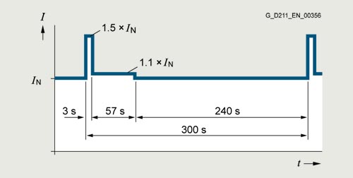
300 s duty cycle based on low overload
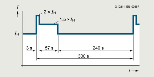
300 s duty cycle based on high overload
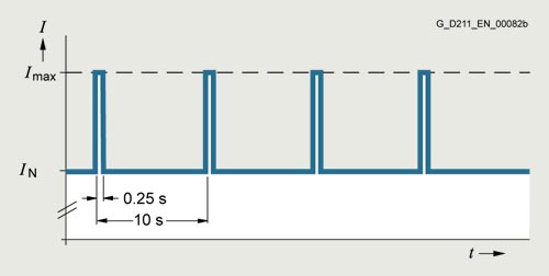
Duty cycle with previous load
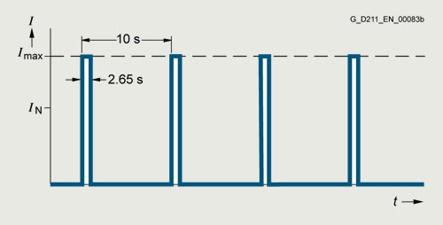
Duty cycle without previous load
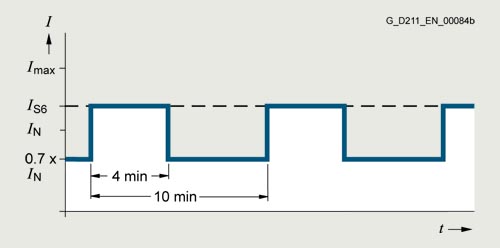
S6 duty cycle with previous load with a load cycle period of 600 s
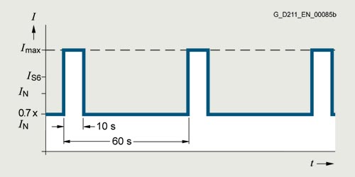
S6 duty cycle with previous load with a load cycle period of 60 s
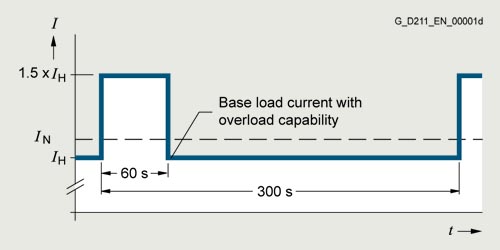
Duty cycle with 60 s overload with a load cycle period of 300 s
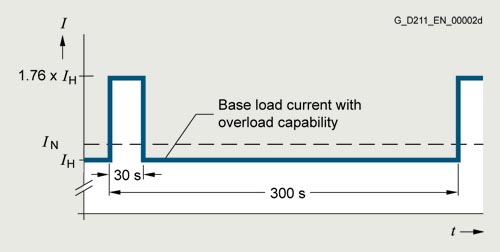
Duty cycle with 30 s overload with a load cycle period of 300 s
Derating data, PM240‑2 Power Modules
Pulse frequency
Rated power 1) |
Rated output current in A for a pulse frequency of |
||||||||
|---|---|---|---|---|---|---|---|---|---|
kW |
hp |
2 kHz |
4 kHz |
6 kHz |
8 kHz |
10 kHz |
12 kHz |
14 kHz |
16 kHz |
0.55 |
0.75 |
3.2 |
3.2 |
2.7 |
2.2 |
1.9 |
1.6 |
1.4 |
1.3 |
0.75 |
1 |
4.2 |
4.2 |
3.6 |
2.9 |
2.5 |
2.1 |
1.9 |
1.7 |
1.1 |
1.5 |
6 |
6 |
5.1 |
4.2 |
3.6 |
2.3 |
2.7 |
2.4 |
1.5 |
2 |
7.4 |
7.4 |
6.3 |
5.2 |
4.4 |
3.7 |
3.3 |
3 |
2.2 |
3 |
10.4 |
10.4 |
8.8 |
7.3 |
6.2 |
5.2 |
4.7 |
4.2 |
3 |
4 |
13.6 |
13.6 |
11.6 |
9.5 |
8.2 |
6.8 |
6.1 |
5.4 |
4 |
5 |
17.5 |
17.5 |
14.9 |
12.3 |
10.5 |
8.8 |
7.9 |
7 |
5.5 |
7.5 |
22 |
22 |
18.7 |
15.4 |
13.2 |
11 |
9.9 |
8.8 |
7.5 |
10 |
28 |
28 |
23.8 |
19.6 |
16.8 |
14 |
12.6 |
11.2 |
11 |
15 |
42 |
42 |
35.7 |
29.4 |
25.2 |
21 |
18.9 |
16.8 |
15 |
20 |
54 |
54 |
45.9 |
37.8 |
32.4 |
27 |
24.3 |
21.6 |
18.5 |
25 |
68 |
68 |
57.8 |
47.6 |
40.8 |
34 |
30.6 |
27.2 |
22 |
30 |
80 |
80 |
68 |
56 |
48 |
40 |
36 |
32 |
30 |
40 |
104 |
104 |
88.4 |
72.8 |
62.4 |
52 |
46.8 |
41.6 |
37 |
50 |
130 |
130 |
110.5 |
91 |
– |
– |
– |
– |
45 |
60 |
154 |
154 |
130.9 |
107.8 |
– |
– |
– |
– |
55 |
75 |
178 |
178 |
151.3 |
124.6 |
– |
– |
– |
– |
1) Rated power based on the rated output current IN. The rated output current Irated is based on the duty cycle for low overload (LO).
Rated power 1) |
Rated output current in A for a pulse frequency of |
||||||||
|---|---|---|---|---|---|---|---|---|---|
kW |
hp |
2 kHz |
4 kHz |
6 kHz |
8 kHz |
10 kHz |
12 kHz |
14 kHz |
16 kHz |
0.55 |
0.75 |
1.7 |
1.7 |
1.4 |
1.2 |
1 |
0.9 |
0.8 |
0.7 |
0.75 |
1 |
2.2 |
2.2 |
1.9 |
1.5 |
1.3 |
1.1 |
1 |
0.9 |
1.1 |
1.5 |
3.1 |
3.1 |
2.6 |
2.2 |
1.9 |
1.6 |
1.4 |
1.2 |
1.5 |
2 |
4.1 |
4.1 |
3.5 |
2.9 |
2.5 |
2.1 |
1.8 |
1.6 |
2.2 |
3 |
5.9 |
5.9 |
5 |
4.1 |
3.5 |
3 |
2.7 |
2.4 |
3 |
4 |
7.7 |
7.7 |
6.5 |
5.4 |
4.6 |
3.9 |
3.5 |
3.1 |
4 |
5 |
10.2 |
10.2 |
8.7 |
7.1 |
6.1 |
5.1 |
4.6 |
4.1 |
5.5 |
7.5 |
13.2 |
13.2 |
11.2 |
9.2 |
7.9 |
6.6 |
5.9 |
5.3 |
7.5 |
10 |
18 |
18 |
15.3 |
12.6 |
10.8 |
9 |
8.1 |
7.2 |
11 |
15 |
26 |
26 |
22.1 |
18.2 |
15.6 |
13 |
11.7 |
10.4 |
15 |
20 |
32 |
32 |
27.2 |
22.4 |
19.2 |
16 |
14.4 |
12.8 |
18.5 |
25 |
38 |
38 |
32.3 |
26.6 |
22.8 |
19 |
17.1 |
15.2 |
22 |
30 |
45 |
45 |
38.3 |
31.5 |
27 |
22.5 |
20.3 |
18 |
30 |
40 |
60 |
60 |
51 |
42 |
36 |
30 |
27 |
24 |
37 |
50 |
75 |
75 |
63.8 |
52.5 |
45 |
37.5 |
33.8 |
30 |
45 |
60 |
90 |
90 |
76.5 |
63 |
54 |
45 |
40.5 |
36 |
55 |
75 |
110 |
110 |
93.5 |
77 |
– |
– |
– |
– |
75 |
100 |
145 |
145 |
123.3 |
101.5 |
– |
– |
– |
– |
90 |
125 |
178 |
178 |
151.3 |
124.6 |
– |
– |
– |
– |
110 |
150 |
205 |
143.5 |
102.5 |
82 |
– |
– |
– |
– |
132 |
200 |
250 |
175 |
125 |
100 |
– |
– |
– |
– |
160 |
250 |
302 |
211.4 |
151 |
120.8 |
– |
– |
– |
– |
200 |
300 |
370 |
259 |
185 |
148 |
– |
– |
– |
– |
250 |
400 |
477 |
333.9 |
238.5 |
190.8 |
– |
– |
– |
– |
1) Rated power based on the rated output current IN. The rated output current Irated is based on the duty cycle for low overload (LO).
Rated power 1) |
Rated output current in A for a pulse frequency of |
||||||||
|---|---|---|---|---|---|---|---|---|---|
kW |
hp |
2 kHz |
4 kHz |
6 kHz |
8 kHz |
10 kHz |
12 kHz |
14 kHz |
16 kHz |
11 |
10 |
14 |
8.4 |
– |
– |
– |
– |
– |
– |
15 |
15 |
19 |
11.4 |
– |
– |
– |
– |
– |
– |
18.5 |
20 |
23 |
13.8 |
– |
– |
– |
– |
– |
– |
22 |
25 |
27 |
16.2 |
– |
– |
– |
– |
– |
– |
30 |
30 |
35 |
21 |
– |
– |
– |
– |
– |
– |
37 |
40 |
42 |
25.2 |
– |
– |
– |
– |
– |
– |
45 |
50 |
52 |
31.2 |
– |
– |
– |
– |
– |
– |
55 |
60 |
62 |
37.2 |
– |
– |
– |
– |
– |
– |
75 |
75 |
80 |
48 |
– |
– |
– |
– |
– |
– |
90 |
100 |
100 |
60 |
– |
– |
– |
– |
– |
– |
110 |
100 |
115 |
69 |
– |
– |
– |
– |
– |
– |
132 |
125 |
142 |
85.2 |
– |
– |
– |
– |
– |
– |
160 |
150 |
171 |
102.6 |
– |
– |
– |
– |
– |
– |
200 |
200 |
208 |
124.8 |
– |
– |
– |
– |
– |
– |
250 |
250 |
250 |
150 |
– |
– |
– |
– |
– |
– |
1) Rated power based on the rated output current IN. The rated output current Irated is based on the duty cycle for low overload (LO).
The permissible motor cable length depends on the cable type and the pulse frequency.
Ambient temperature
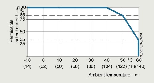
Permissible output current as a function of ambient temperature for low overload (LO) for PM240‑2 Power Modules
FSA to FSC at 200 V and 400 V
FSD to FSF at 690 V
FSG at 400 V and 690 V
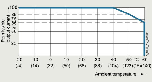
Permissible output current as a function of ambient temperature for low overload (LO) for PM240‑2 Power Modules
FSD to FSF at 200 V and 400 V
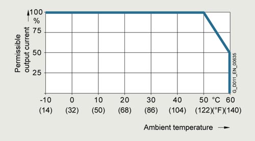
Permissible output current as a function of ambient temperature for high overload (HO) for PM240-2 Power Modules
FSA to FSC at 200 V and 400 V
FSD to FSF at 690 V
FSG at 400 V and 690 V
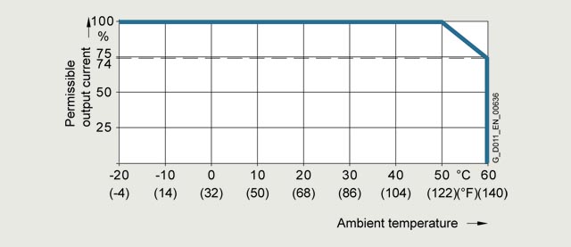
Permissible output current as a function of ambient temperature for high overload (HO) for PM240-2 Power Modules
FSD to FSF at 200 V and 400 V
The operating temperature ranges of the Control Units should be taken into account. The temperature ranges are specified in the section Technical specifications under Control Units.
Installation altitude
Permissible line supplies depending on the installation altitude
- Installation altitude up to 2000 m (6562 ft) above sea level
- Connection to every supply system permitted for the converter
- Installation altitudes between 2000 m and 4000 m (6562 ft and 13124 ft) above sea level
- Connection to a TN system with grounded neutral point
- TN systems with grounded line conductor are not permitted
- The TN line system with grounded neutral point can also be supplied using an isolation transformer
- The phase against phase voltage does not have to be reduced
The connected motors, power elements and components must be considered separately.
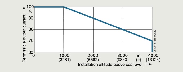
Permissible output current as a function of the installation altitude for PM240‑2 Power Modules at 40 °C for low overload (LO)
System operating voltage
The rated output current is constant within the respective supply voltage range.
More information on the derating data of the PM240‑2 Power Modules is available in the Hardware Installation Manual on the internet at:
www.siemens.com/sinamics-g120/documentation
Чертеж
PM240‑2 Power Modules, standard variant
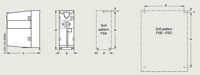
Principle dimension drawing and drill pattern for PM240-2 Power Modules, standard variant, with/without integrated line filter
Frame size |
Dimensions in mm (inches) |
Drilling dimensions in mm (inches) |
Cooling clearance 1) in mm (inches) |
Mounting |
||||||
|---|---|---|---|---|---|---|---|---|---|---|
a |
b |
c |
d |
e |
f |
top |
bottom |
front |
With bolts |
|
PM240-2 Power Modules, standard variant, with/without integrated line filter | ||||||||||
FSA |
73 |
196 |
165 |
62.3 |
186 |
6 |
80 |
100 |
0 |
3 × M4 |
FSB |
100 |
292 |
165 |
80 |
281 |
6 |
80 |
100 |
0 |
4 × M4 |
FSC |
140 |
355 |
165 |
120 |
343 |
6 |
80 |
100 |
0 |
4 × M5 |
FSD |
200 |
472 |
237 |
170 |
430 |
7 |
300 |
350 |
100 |
4 × M5 |
FSE |
275 |
551 |
237 |
230 |
509 |
8.5 |
300 |
350 |
100 |
4 x M6 |
FSF |
305 |
708 |
357 |
270 |
680 |
13 |
300 |
350 |
100 |
4 × M8 |
FSG |
305 |
1000 |
357 |
265 |
970.5 |
15 |
300 |
350 |
100 |
4 × M10 |
1) The Power Modules can be mounted side by side. A side clearance of 1 mm (0.04 in) is recommended for tolerance-related reasons.