


















Обзор
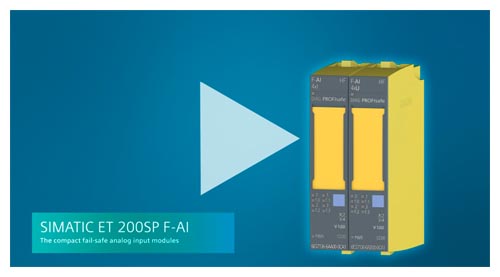
SIMATIC ET 200SP Safety F-AI-4xU video
SIMATIC ET 200SP Safety F-AI-4xI video
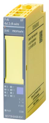
Analog fail-safe input modules:
- F-AI 4xI 0(4)..20 mA 2/4-wire High Feature for BU types A0 and A1, color code CC00
- F-AI 4xU 0..10 V HF, BU type A0, A1, color code CC00
Important properties:
- 4-channel analog fail-safe digital inputs for ET 200SP
- 4 analog inputs with galvanic isolation between channels and backplane bus
- Measuring ranges: (0)4...20 mA and 0..10 V
- Possibility of connecting current and voltage sensors for measuring temperature, pressure, flow, level, distance measurement, etc.
- Short-circuit-proof power supply for analog sensors
- Resolution: 16 bits including sign
- Certified up to SIL 3 (IEC 61508), PL e (ISO 13849)
- Can be plugged onto type A0 and A1 BaseUnits (BU)
- LED display for error, operation, supply voltage, and status
- Interference frequency suppression, smoothing
- Diagnostics: wire break, short-circuit, high/low limit violation
- Firmware update
- Identification data I&M
- Value status
- Clear labeling on front of module
- Plain text identification of the module type and function class
- 2D matrix code (order and serial number)
- Connection diagram
- Color coding of the DI module type: white
- Hardware and firmware version
- Color code CC for module-specific color coding of the potentials at the terminals of the BU
- Complete Article No.
- Optional labeling accessories
- Labeling strips
- Equipment labeling plate
- Optional module-specific color coding of the terminals according to the color code CC
- Optional system-integrated shield connection
- The modules support PROFIsafe in both PROFIBUS and PROFINET configurations. Can be used with all fail-safe SIMATIC S7 CPUs.
Область применения
The fail-safe ET 200SP modules can be used to implement the safety-related application requirements as an integrated part of the overall automation. The safety functions required for fail-safe operation are integrated in the modules. Communication with the fail-safe SIMATIC S7 CPUs is performed by means of PROFIsafe.
The modules can be operated both in centralized and distributed configurations.
Дизайн
Suitable BaseUnits
BaseUnits with an appropriate number of terminals are available for single and multi-conductor connections.
A light BaseUnit opens a new load group. The supply voltage to the sensors must be fed via this BU. The first BU next to the interface module must always be a light BU.
A dark BaseUnit forwards the supply voltage of the adjacent light BaseUnit on the left via self-assembling voltage buses. A new infeed is therefore only required on the next light BaseUnit to the right.
All variants that correspond to the BU type of the I/O module can be used as BaseUnits.
Color identification of the terminals
The potentials at the terminals of the BaseUnit are defined by the I/O module. Optionally, the potentials of the terminals can be identified by module-specific color-coding labels to prevent wiring errors. The color-coded label that matches the respective I/O module is defined by the color code CCxx of the I/O module. This color code is also printed on the front of the module.
System-integrated shield connection
A shield connection is available for quick and easy cable shield installation that is both space-saving as well as EMC optimized. It consists of one shield connection element that can be plugged onto the BaseUnit and one shield terminal for each module. The low-impedance connection to the functional ground (DIN rail) is achieved without any additional wiring by the user.
Технические данные
Article number |
6ES7136-6AA00-0CA1 |
6ES7136-6AB00-0CA1 |
|
|---|---|---|---|
ET 200SP, F-AI 4XI 0(4)..20mA HF |
ET 200SP, F-AI 4xU 0..10V HF |
||
General information |
|||
Product type designation |
F-AI 4xI 0(4)..20mA 2-/4-wire HF |
F-AI 4XU 0..10V HF |
|
Firmware version |
|||
|
Yes |
Yes |
|
usable BaseUnits |
BU type A0, A1 |
BU type A0, A1 |
|
Color code for module-specific color-coded label |
CC00 |
CC00 |
|
Product function |
|||
|
Yes; I&M0 to I&M3 |
Yes; I&M0 to I&M3 |
|
Engineering with |
|||
|
V15 with HSP 203 |
V16 with HSP 308 |
|
Operating mode |
|||
|
Yes |
||
|
No |
||
|
No |
||
CiR - Configuration in RUN |
|||
Reparameterization possible in RUN |
No |
No |
|
Calibration possible in RUN |
No |
No |
|
Supply voltage |
|||
Rated value (DC) |
24 V |
24 V |
|
permissible range, lower limit (DC) |
19.2 V |
19.2 V |
|
permissible range, upper limit (DC) |
28.8 V |
28.8 V |
|
Reverse polarity protection |
Yes |
Yes |
|
power supply according to NEC Class 2 required |
No |
No |
|
Input current |
|||
Current consumption (rated value) |
0.38 A |
0.38 A |
|
Current consumption, max. |
0.4 A |
0.4 A |
|
Encoder supply |
|||
24 V encoder supply |
|||
|
Yes; min. L+ (-1.5 V) |
Yes; min. L+ (-1.5 V) |
|
|
Yes |
Yes |
|
|
300 mA; total current of all encoders/channels |
300 mA; total current of all encoders/channels |
|
Power |
|||
Power consumption from the backplane bus |
70 mW |
70 mW |
|
Power loss |
|||
Power loss, typ. |
2 W |
2 W |
|
Address area |
|||
Address space per module |
|||
|
14 byte; S7-300/400F CPU, 13 byte |
14 byte; S7-300/400F CPU, 13 byte |
|
|
5 byte; S7-300/400F CPU, 4 byte |
5 byte; S7-300/400F CPU, 4 byte |
|
Hardware configuration |
|||
Automatic encoding |
Yes |
Yes |
|
|
Yes |
||
|
Yes |
||
Analog inputs |
|||
Number of analog inputs |
4 |
4 |
|
|
4 |
||
|
4 |
||
permissible input voltage for voltage input (destruction limit), max. |
36 V |
||
permissible input current for current input (destruction limit), max. |
35 mA |
||
Input ranges (rated values), voltages |
|||
|
Yes |
||
|
16 kΩ |
||
Input ranges (rated values), currents |
|||
|
Yes |
||
|
125 Ω |
||
|
Yes |
||
|
125 Ω |
||
Cable length |
|||
|
1 000 m |
200 m |
|
Analog value generation for the inputs |
|||
Measurement principle |
Sigma Delta |
Sigma Delta |
|
Integration and conversion time/resolution per channel |
|||
|
16 bit |
16 bit |
|
|
Yes |
Yes |
|
|
20 / 16,667 |
20 / 16,667 |
|
|
50 / 60 Hz |
50 / 60 Hz |
|
Smoothing of measured values |
|||
|
7 |
7 |
|
|
Yes |
Yes |
|
|
Yes; 1x conversion cycle time |
Yes; 1x conversion cycle time |
|
|
Yes; 2x / 4x conversion cycle time |
Yes; 2x / 4x conversion cycle time |
|
|
Yes; 8x / 16x conversion cycle time |
Yes; 8x / 16x conversion cycle time |
|
|
Yes; 32x / 64x conversion cycle time |
Yes; 32x / 64x conversion cycle time |
|
|
Yes |
||
Encoder |
|||
Connection of signal encoders |
|||
|
Yes |
||
|
Yes |
||
|
650 Ω |
||
|
Yes |
||
Errors/accuracies |
|||
Linearity error (relative to input range), (+/-) |
0.1 % |
0.1 % |
|
Temperature error (relative to input range), (+/-) |
0.023 %/K |
0.023 %/K |
|
Repeat accuracy in steady state at 25 °C (relative to input range), (+/-) |
0.1 % |
0.1 % |
|
Operational error limit in overall temperature range |
|||
|
2 % |
||
|
2 % |
||
Basic error limit (operational limit at 25 °C) |
|||
|
0.1 % |
||
|
0.1 % |
||
Interference voltage suppression for f = n x (f1 +/- 1 %), f1 = interference frequency |
|||
|
40 dB |
40 dB |
|
|
10 V |
||
|
70 dB |
70 dB |
|
Interrupts/diagnostics/status information |
|||
Diagnostics function |
Yes |
Yes |
|
Alarms |
|||
|
Yes |
Yes |
|
|
No |
No |
|
Diagnoses |
|||
|
Yes |
Yes |
|
|
Yes |
Yes |
|
|
Yes |
||
Diagnostics indication LED |
|||
|
Yes; green LED |
Yes; green LED |
|
|
Yes; red LED |
Yes; red LED |
|
|
Yes; green PWR LED |
Yes; green PWR LED |
|
|
Yes; green LED |
Yes; green LED |
|
|
Yes; red LED |
Yes; red LED |
|
|
Yes; green/red DIAG LED |
Yes; green/red DIAG LED |
|
Potential separation |
|||
Potential separation channels |
|||
|
No |
No |
|
|
Yes |
Yes |
|
|
Yes |
Yes |
|
Permissible potential difference |
|||
between the inputs (UCM) |
10 Vpp |
10 Vpp |
|
Isolation |
|||
Isolation tested with |
707 V DC (type test) |
707 V DC (type test) |
|
Standards, approvals, certificates |
|||
Ecological footprint |
|||
|
Yes |
Yes |
|
Global warming potential |
|||
|
88.3 kg |
88.3 kg |
|
|
13.1 kg |
13.1 kg |
|
|
76.6 kg |
76.6 kg |
|
|
-1.37 kg |
-1.37 kg |
|
Highest safety class achievable in safety mode |
|||
|
PLe |
PLe |
|
|
Cat. 4 |
Cat. 4 |
|
|
SIL 3 |
SIL 3 |
|
Probability of failure (for service life of 20 years and repair time of 100 hours) |
|||
|
< 5.00E-05 |
< 5.00E-05 |
|
|
< 1.00E-09 1/h |
< 1.00E-09 1/h |
|
Ambient conditions |
|||
Ambient temperature during operation |
|||
|
0 °C |
0 °C |
|
|
60 °C |
60 °C |
|
|
0 °C |
0 °C |
|
|
50 °C |
50 °C |
|
Dimensions |
|||
Width |
15 mm |
15 mm |
|
Height |
73 mm |
73 mm |
|
Depth |
58 mm |
58 mm |
|
Weights |
|||
Weight, approx. |
48 g |
48 g |
|