


















Обзор
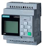
- F модуль ввода дискретных сигналов для S7-1200F.
- Использование в системах обеспечения безопасности.
- Встроенная поддержка функций обеспечения безопасности.
- Обмен данными с F-CPU на основе механизмов PROFIsafe.
- Гибкая адаптация контроллера к требованиям решаемых задач.
- Получение дополнительных каналов ввода дискретных сигналов.
- Использование только в системе локального ввода-вывода программируемого контроллера.
Область применения
F модули позволяют использовать программируемые контроллеры SIMATIC S7-1200 для построения систем противоаварийной защиты и обеспечения безопасности. Функции обеспечения безопасности поддерживаются на уровне F модулей. Для обмена данными с SIMATIC S7 F-CPU используются механизмы PROFIsafe.
Модули могут использоваться только в системе локального ввода-вывода программируемого контроллера S7-1200.
Дизайн
- 16 входов (SIL 2/ категория 3/ PL d), 8 входов (SIL 3/ категория 3 или 4/ PL e) или смешанное использование различных видов F входов.
- Номинальное входное напряжение =24 В.
- Подключение контактных датчиков, а также 3- или 4-проводное подключение бесконтактных датчиков BERO.
- Два встроенных блока питания датчиков с защитой от коротких замыканий для питания двух групп входов. По 8 входов в каждой группе. Поддержка схем с питанием датчиков от внешних блоков питания.
- Индикатор наличия ошибок в работе модуля (DIAG; зеленый или красный светодиод).
- Индикаторы состояний входных каналов (зеленый светодиод на канал).
- Индикаторы наличия ошибок в работе каналов (красный светодиод на канал).
- Идентификационные данные на корпусе модуля:
- Версия аппаратуры и встроенного программного обеспечения.
- Полный заказной номер.
Технические данные
Article number |
6AG1226-6BA32-5XB0 |
|
|---|---|---|
SIPLUS S7-1200 SM 1226 F-DI 16x24VDC |
||
General information |
||
Product type designation |
SM 1226, F-DI 16x24 V DC |
|
based on |
6ES7226-6BA32-0XB0 |
|
Supply voltage |
||
Rated value (DC) |
24 V |
|
permissible range, lower limit (DC) |
20.4 V |
|
permissible range, upper limit (DC) |
28.8 V |
|
power supply according to NEC Class 2 required |
No |
|
Input current |
||
from backplane bus 5 V DC, max. |
155 mA; Current consumption (SM Bus, 5 V DC): 155 mA |
|
Digital inputs |
||
|
130 mA; 130 mA + 6 mA / input used + any Vs1/Vs2 current used |
|
Power loss |
||
Power loss, typ. |
7 W |
|
Digital inputs |
||
Number of digital inputs |
16; 16 (1oo1) or 8 (1oo2); Note: You can individually assign each pair of inputs "a.x" and "b.x" as a single (1oo2)-channel or as 2 separate (1oo1)-channels |
|
Number of simultaneously controllable inputs |
||
horizontal installation |
||
|
16; 16 inputs at 55 °C horizontal |
|
vertical installation |
||
|
16; 16 inputs at 45 °C vertical |
|
Input voltage |
||
|
-30 V DC to +5 V DC |
|
|
15 V DC to 30 V DC |
|
Input current |
||
|
0.5 mA |
|
|
5 mA |
|
Input delay (for rated value of input voltage) |
||
for standard inputs |
||
|
Yes; 0.8 / 1.6 / 3.2 / 6.4 / 12.8 ms |
|
Cable length |
||
|
200 m; unshielded with input filter time of 1.6 ms to 12.6 ms (With an input delay of 0.8 ms, shielded cables must be used for the digital inputs and the sensor supply) |
|
|
200 m; Shielded with input filter time of 0.8 ms to 12.6 s (With an input delay of 0.8 ms, shielded cables must be used for the digital inputs and the sensor supply) |
|
Interrupts/diagnostics/status information |
||
Diagnostics indication LED |
||
|
Yes |
|
Degree and class of protection |
||
IP degree of protection |
IP20 |
|
Standards, approvals, certificates |
||
Highest safety class achievable in safety mode |
||
|
1-channel, Category 3, PL d; 2-channel, Category 3 or 4, PL e |
|
|
SIL 2 (single-channel), SIL 3 (two-channel) |
|
Probability of failure (for service life of 20 years and repair time of 100 hours) |
||
|
< 5.00E-04 |
|
|
< 1.00E-05 |
|
|
< 1.00E-08 1/h |
|
|
< 1.00E-10 1/h |
|
Ambient conditions |
||
Free fall |
||
|
0.3 m; five times, in product package |
|
Ambient temperature during operation |
||
|
-25 °C; = Tmin |
|
|
55 °C; = Tmax |
|
|
5°C to 55°C, 3°C / minute |
|
Ambient temperature during storage/transportation |
||
|
-40 °C |
|
|
70 °C |
|
Air pressure acc. to IEC 60068-2-13 |
||
|
660 hPa |
|
|
1 140 hPa |
|
Altitude during operation relating to sea level |
||
|
5 000 m |
|
|
Tmin ... Tmax at 1 140 hPa ... 795 hPa (-1 000 m ... +2 000 m) // Tmin ... (Tmax - 10 K) at 795 hPa ... 658 hPa (+2 000 m ... +3 500 m) // Tmin ... (Tmax -20 K) at 658 hPa ... 540 hPa (+3 500 m ... +5 000 m) |
|
Relative humidity |
||
|
100 %; RH incl. condensation/frost (no commissioning under condensation conditions) |
|
Resistance |
||
Coolants and lubricants |
||
|
Yes |
|
Use in stationary industrial systems |
||
|
Yes; Class 3B2 mold, fungus and dry rot spores (with the exception of fauna); Class 3B3 on request |
|
|
Yes; Class 3C4 (RH < 75 %) incl. salt spray acc. to EN 60068-2-52 (severity degree 3); * |
|
|
Yes; Class 3S4 incl. sand, dust, * |
|
Use on ships/at sea |
||
|
Yes; Class 6B2 mold and fungal spores (excluding fauna); Class 6B3 on request |
|
|
Yes; Class 6C3 (RH < 75 %) incl. salt spray acc. to EN 60068-2-52 (severity degree 3); * |
|
|
Yes; Class 6S3 incl. sand, dust; * |
|
Usage in industrial process technology |
||
|
Yes; Class 3 (excluding trichlorethylene) |
|
|
Yes; Level GX group A/B (excluding trichlorethylene; harmful gas concentrations up to the limits of EN 60721-3-3 class 3C4 permissible); level LC3 (salt spray) and level LB3 (oil) |
|
Remark |
||
|
* The supplied plug covers must remain in place over the unused interfaces during operation! |
|
Conformal coating |
||
|
Yes; Class 2 for high reliability |
|
|
Yes; Type 1 protection |
|
|
Yes; Discoloration of coating possible during service life |
|
|
Yes; Conformal coating, Class A |
|
Mechanics/material |
||
Enclosure material (front) |
||
|
Yes |
|
Dimensions |
||
Width |
70 mm |
|
Height |
100 mm |
|
Depth |
75 mm |
|
Weights |
||
Weight, approx. |
250 g |
|