


















Дизайн
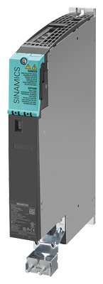
Single Motor Module in booksize format C/D type, 3 A to 30 A
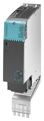
Single Motor Module in booksize format C type, 45 A and 60 A, with optional shield connection plate
The Single Motor Modules in booksize format feature the following connections and interfaces as standard:
- 2 DC link connections via integrated DC link busbars
- 1 electronics power supply connection via integrated 24 V DC bars
- 3 DRIVE‑CLiQ sockets
- 1 motor connection via connector X1 for C/D type 3 A to 30 A (not included in the scope of delivery)
- 1 safe standstill input
- 1 safe motor brake control
- 1 temperature sensor input for KTY84‑130, Pt1000 or PTC (Pt1000 can be used from firmware V4.7 HF17)
- 2 PE (protective earth) connections – a PE connection is integrated in the connector for C/D types 3 A to 30 A
The status of the Motor Modules is indicated via two multi-color LEDs.
Motor Modules 3 A to 30 A are supplied with a mounted shield connection plate. The associated shield connection clamp can be found in the Terminal Kit supplied. A shield connection plate is optionally available for Motor Modules 45 A to 200 A. On these modules, the motor cable shield can be connected using a shield connection clamp or a hose clip.
Motor Modules in booksize format C/D types, 3 A to 60 A
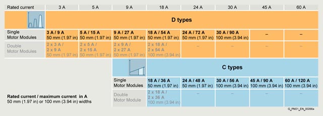
Overview of available Single Motor Modules in booksize format C/D types
- C type: Optimized for continuous load with up to 200 % overload (continuous motion)
- D type: Optimized for highly dynamic, intermittent duty cycles with up to 300 % overload (discontinuous motion)
Devices in booksize format C/D types are optimized for multi-axis applications and are mounted next to one another. The connection for the common DC link is an integral feature. The device is internally air cooled.
The Motor Modules in booksize format C/D types have been developed to be fully compatible with the booksize series regarding spare parts and offer the following advantages:
- The portfolio is extended by Single Motor Modules 18 A (C type), 24 A (C/D types) and 30 A (D type), as well as by a Double Motor Module 18 A (D type).
- The width of Motor Modules 45 A and 60 A has been reduced from 150 mm to 100 mm, which makes a significant contribution toward saving space in the cabinet
- The amount of space required beneath the Motor Modules has been reduced thanks to improvements in the design and a new motor plug connector
- With the new motor plug connector design, the brake conductors and the PE connection are integrated directly in the plug connector
- The motor connections on the Double Motor Module are located side by side, resulting in a significantly improved level of accessibility
- The fan can be simply replaced without having to remove the Motor Module
The signal cable shield can be connected to the Motor Module by means of a shield connection clamp, e.g. Weidmüller type KLBUE 3-8 SC.
The scope of delivery of the Motor Modules includes:
- DRIVE‑CLiQ cable appropriate to the width of the Motor Module for connection to the adjacent Motor Module, length = width of Motor Module + 0.06 m (0.20 ft)
- Jumper for connecting the 24 V DC busbar to the adjacent Motor Module
- Connector X21
- Connector X11 for the motor brake connection
(for Motor Modules 45 A to 200 A) - 2 blanking plugs for sealing unused DRIVE-CLiQ sockets
- Fan insert for the 132 A and 200 A Motor Modules
(the voltage for the fan insert is supplied by the Motor Module) - 1 shield connection plate with shield connection clamp
(for Motor Modules 3 A to 30 A) - 1 set of warning labels in 36 languages
Интеграция
The Single Motor Module receives its control information via DRIVE-CLiQ from:
- CU320‑2 Control Unit
- SINUMERIK 840D sl
- SINUMERIK ONE
- SINUMERIK MC
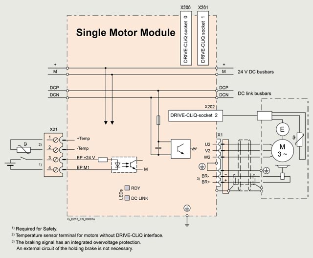
Connection example of Single Motor Modules in booksize format C/D types, 3 A to 30 A
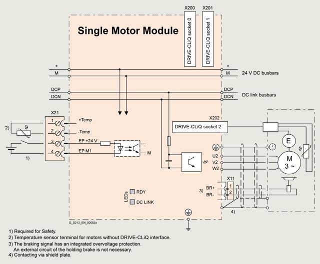
Connection example of Single Motor Modules in booksize format C type, 45 A and 60 A
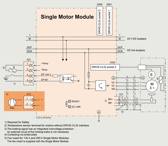
Connection example of Single Motor Modules in booksize format, 85 A to 200 A
Технические данные
|
Single Motor Module in booksize format 6SL3120-1TE... |
|
|---|---|
|
DC link voltage (up to 2000 m (6562 ft) above sea level) |
510 ... 720 V DC |
Output frequency |
|
|
0 ... 650 Hz 1) 2) 3) |
|
0 ... 300 Hz 2) |
|
0 ... 600 Hz 2) 3) |
Electronics power supply |
24 V DC -15 %/+20 % |
Type of cooling |
Internal air cooling (power units with increased air cooling by built-in fan) |
|
Permissible ambient and coolant temperature (air) during operation for line-side components, Line Modules and Motor Modules |
0 ... 40 °C (32 ... 104 °F) without derating, |
Installation altitude |
Up to 1000 m (3281 ft) above sea level without derating, |
Declarations of conformity |
CE (Low-Voltage and EMC Directives) |
Certificate of suitability |
cULus |
Safety Integrated |
Safety Integrity Level 2 (SIL 2) according to IEC 61508, For further information, see section Safety Integrated. |
1) At rated output current (max. output frequency 1300 Hz for 62.5 µs current control cycle, 8 kHz pulse frequency, 60 % permissible output current).
2) Note the correlation between max. output frequency, pulse frequency and current derating. For further information, see section Configuration notes.
3) The output frequency is currently limited to 550 Hz. The specified values apply to systems with license for high output frequency. For further information, see section Control Units and
DC link voltage 510 ... 720 V DC |
Single Motor Module in booksize format |
||||
|---|---|---|---|---|---|
Internal air cooling C type |
6SL3120-... |
– |
– |
– |
1TE21-8AC0 |
Internal air cooling D type |
6SL3120-... |
1TE13-0AD0 |
1TE15-0AD0 |
1TE21-0AD0 |
1TE21-8AD0 |
Output current |
|||||
|
A |
3 |
5 |
9 |
18 |
|
A |
2.6 |
4.3 |
7.7 |
15.3 |
|
A |
4 |
6.7 |
12 |
24 |
|
|||||
|
A |
– |
– |
– |
36 |
|
A |
9 |
15 |
27 |
54 |
Type rating 1) |
|||||
|
kW (hp) |
1.6 (1.5) |
2.7 (3) |
4.8 (5) |
9.7 (10) |
|
kW (hp) |
1.4 (1) |
2.3 (2.5) |
4.1 (5) |
8.2 (10) |
Rated pulse frequency |
kHz |
4 |
4 |
4 |
4 |
DC link current Id2) |
A |
3.6 |
6 |
11 |
22 |
Current carrying capacity |
|||||
|
A |
100 3) |
100 3) |
100 3) |
100 3) |
|
A |
20 |
20 |
20 |
20 |
DC link capacitance |
μF |
110 |
110 |
110 |
220 |
|
Current requirement At 24 V DC, max. |
A |
0.75 |
0.75 |
0.75 |
0.75 |
|
Power loss 5) typ. 6)/max. |
kW |
0.03/0.05 |
0.04/0.07 |
0.06/0.1 |
0.14/0.19 |
Cooling air requirement |
m3/s (ft3/s) |
0.009 (0.32) |
0.009 (0.32) |
0.009 (0.32) |
0.009 (0.32) |
|
Sound pressure level LpA (1 m) |
dB |
<60 |
<60 |
<60 |
<60 |
|
Motor connection U2, V2, W2 |
Plug-in connector (X1) 7), |
Plug-in connector (X1) 7), |
Plug-in connector (X1) 7), |
Plug-in connector (X1) 7), |
|
PE connection |
M5 screw |
M5 screw |
M5 screw |
M5 screw |
|
Motor brake connection |
Integrated into the plug-in motor connector (X1), |
Integrated into the plug-in motor connector (X1), |
Integrated into the plug-in motor connector (X1), |
Integrated into the plug-in motor connector (X1), |
|
Motor cable length, max. |
|||||
|
m (ft) |
50 (164) |
50 (164) |
50 (164) |
70 (230) |
|
m (ft) |
75 (246) |
75 (246) |
75 (246) |
100 (328) |
Degree of protection |
IP20 |
IP20 |
IP20 |
IP20 |
|
Dimensions |
|||||
|
mm (in) |
50 (1.97) |
50 (1.97) |
50 (1.97) |
50 (1.97) |
|
mm (in) |
380 (14.96) |
380 (14.96) |
380 (14.96) |
380 (14.96) |
|
mm (in) |
270 (10.63) |
270 (10.63) |
270 (10.63) |
270 (10.63) |
Weight, approx. |
kg (lb) |
4.6 (10.1) |
4.6 (10.1) |
4.6 (10.1) |
4.6 (10.1) |
1) Rated power of a typical standard asynchronous (induction) motor at 400 V AC.
2) Rated DC link current for dimensioning an external DC connection.
3) With reinforced DC link bridges, (Article No. 6SL3162-2BB00-0AA0) 200 A is possible (Accessories).
4) If, due to a number of Line Modules and Motor Modules being mounted side by side, the current carrying capacity exceeds 20 A, an additional 24 V DC connection using a 24 V terminal adapter is required (max. cross-section 6 mm2, max. fuse protection 20 A).
5) Power loss of Motor Module at rated power including losses of 24 V DC electronics power supply.
6) At max. motor cable length 30 m (98.43 ft), pulse frequency 4 kHz and DC link voltage 540 ... 600 V.
7) Connector not included in scope of delivery, see Accessories.
DC link voltage 510 ... 720 V DC |
Single Motor Module in booksize format |
||||
|---|---|---|---|---|---|
Internal air cooling C type |
6SL3120-... |
1TE22-4AC0 |
1TE23-0AC0 |
1TE24-5AC0 |
1TE26-0AC0 |
Internal air cooling D type |
6SL3120-... |
1TE22-4AD0 |
1TE23-0AD0 |
– |
– |
Output current |
|||||
|
A |
24 |
30 |
45 |
60 |
|
A |
20.4 |
25.5 |
38 |
51 |
|
A |
32 |
40 |
60 |
80 |
|
|||||
|
A |
48 |
56 |
90 8) |
120 8) |
|
A |
72 |
90 |
– |
– |
Type rating 1) |
|||||
|
kW (hp) |
12.9 (15) |
16 (20) |
24 (30) |
32 (40) |
|
kW (hp) |
10.9 (15) |
13.7 (18) |
21 (25) |
28 (40) |
Rated pulse frequency |
kHz |
4 |
4 |
4 |
4 |
DC link current Id2) |
A |
29 |
36 |
54 |
72 |
Current carrying capacity |
|||||
|
A |
100 3) |
200 |
200 |
200 |
|
A |
20 |
20 |
20 |
20 |
DC link capacitance |
μF |
390 |
705 |
1230 |
1410 |
|
Current requirement At 24 V DC, max. |
A |
1.0 |
0.8 |
0.9 |
0.9 |
|
Power loss 5) typ. 6)/max. |
kW |
0.19/0.20 |
0.26/0.31 |
0.34/0.36 |
0.46/0.48 |
Cooling air requirement |
m3/s (ft3/s) |
0.0147 (0.52) |
0.0155 (0.55) |
0.0233 (0.82) |
0.0233 (0.82) |
|
Sound pressure level LpA (1 m) |
dB |
<68 |
<60 |
<71 |
<71 |
|
Motor connection U2, V2, W2 |
Plug-in connector (X1) 7), |
Plug-in connector (X1) 7), |
M6 screw studs (X1) |
M6 screw studs (X1) |
|
Shield connection |
At the shield connection plate of the Motor Modules |
At the shield connection plate of the Motor Modules |
See Accessories |
See Accessories |
|
PE connection |
M5 screw |
M5 screw |
M5 screw |
M5 screw |
|
Motor brake connection |
Integrated into the plug-in motor connector (X1), |
Integrated into the plug-in motor connector (X1), |
Plug-in connector (X11), 24 V DC, 2 A |
Plug-in connector (X11), 24 V DC, 2 A |
|
Motor cable length, max. |
|||||
|
m (ft) |
70 (230) |
100 (328) |
100 (328) |
100 (328) |
|
m (ft) |
100 (328) |
150 (492) |
150 (492) |
150 (492) |
Degree of protection |
IP20 |
IP20 |
IP20 |
IP20 |
|
Dimensions |
|||||
|
mm (in) |
50 (1.97) |
100 (3.94) |
100 (3.94) |
100 (3.94) |
|
mm (in) |
380 (14.96) |
380 (14.96) |
380 (14.96) |
380 (14.96) |
|
mm (in) |
270 (10.63) |
270 (10.63) |
270 (10.63) |
270 (10.63) |
Weight, approx. |
kg (lb) |
4.7 (10.4) |
7.9 (17.4) |
8.5 (18.7) |
8.6 (19) |
1) Rated power of a typical standard asynchronous (induction) motor at 400 V AC.
2) Rated DC link current for dimensioning an external DC connection.
3) With reinforced DC link bridges, (Article No. 6SL3162-2BB00-0AA0) 200 A is possible (Accessories).
4) If, due to a number of Line Modules and Motor Modules being mounted side by side, the current carrying capacity exceeds 20 A, an additional 24 V DC connection using a 24 V terminal adapter is required (max. cross-section 6 mm2, max. fuse protection 20 A).
5) Power loss of Motor Module at rated power including losses of 24 V DC electronics power supply.
6) At max. motor cable length 30 m (98.43 ft), pulse frequency 4 kHz and DC link voltage 540 ... 600 V.
7) Connector not included in scope of delivery, see Accessories.
8) The specified values are valid as from firmware V4.8.
DC link voltage 510 ... 720 V DC |
Single Motor Module in booksize format |
|||
|---|---|---|---|---|
Internal air cooling |
6SL3120-... |
1TE28-5AA3 |
1TE31-3AA3 |
1TE32-0AA4 |
Output current |
||||
|
A |
85 |
132 |
200 |
|
A |
68 |
105 |
141 |
|
A |
110 |
150 |
230 |
|
A |
141 |
210 |
282 |
Type rating 1) |
||||
|
kW (hp) |
46 (60) |
71 (100) |
107 (150) |
|
kW (hp) |
37 (50) |
57 (75) |
76 (100) |
Rated pulse frequency |
kHz |
4 |
4 |
4 |
DC link current Id2) |
A |
102 |
158 |
200 |
Current carrying capacity |
||||
|
A |
200 |
200 |
200 |
|
A |
20 |
20 |
20 |
DC link capacitance |
μF |
1880 |
2820 |
3995 |
|
Current requirement At 24 V DC, max. |
A |
1.5 |
1.5 |
1.5 |
|
Power loss 4) typ. 5)/max. |
kW |
0.77/0.79 |
1.26/1.29 |
2.03/2.09 |
Cooling air requirement |
m3/s (ft3/s) |
0.044 (1.6) |
0.144 (5.1) |
0.144 (5.1) |
|
Sound pressure level LpA (1 m) |
dB |
<60 |
<73 |
<73 |
|
Motor connection U2, V2, W2 |
M8 screw studs (X1) |
M8 screw studs (X1) |
M8 screw studs (X1) |
|
|
mm2 |
2.5 ... 95, 2 × 35 |
2.5 ... 120, 2 × 50 |
2.5 ... 120, 2 × 50 |
Shield connection |
See Accessories |
See Accessories |
See Accessories |
|
PE connection |
M6 screw |
M8 screw |
M8 screw |
|
Motor brake connection |
Plug-in connector (X11), 24 V DC, 2 A |
Plug-in connector (X11), 24 V DC, 2 A |
Plug-in connector (X11), 24 V DC, 2 A |
|
Motor cable length, max. |
||||
|
m (ft) |
100 (328) |
100 (328) |
100 (328) |
|
m (ft) |
150 (492) |
150 (492) |
150 (492) |
Degree of protection |
IP20 |
IP20 |
IP20 |
|
Dimensions |
||||
|
mm (in) |
200 (7.87) |
300 (11.81) |
300 (11.81) |
|
mm (in) |
380 (14.96) |
380 (14.96) |
380 (14.96) |
|
mm (in) |
– |
629 (24.76) |
629 (24.76) |
|
mm (in) |
270 (10.63) |
270 (10.63) |
270 (10.63) |
Weight, approx. |
kg (lb) |
14.8 (32.6) |
21 (46.3) |
21 (46.3) |
1) Rated power of a typical standard asynchronous (induction) motor at 400 V AC.
2) Rated DC link current for dimensioning an external DC connection.
3) If, due to a number of Line Modules and Motor Modules being mounted side-by-side, the current carrying capacity exceeds 20 A, an additional 24 V DC connection using a 24 V terminal adapter is required (max. cross-section 6 mm2, max. fuse protection 20 A).
4) Power loss of Motor Module at rated power including losses of 24 V DC electronics power supply.
5) At max. motor cable length 30 m (98.43 ft), pulse frequency 4 kHz and DC link voltage 540 ... 600 V.
6) The fan is supplied with the Motor Module and must be installed before the Motor Module is commissioned.
Характеристика
Overload capability
Motor Modules in booksize format C type 3 A to 60 A and booksize format 85 A to 200 A
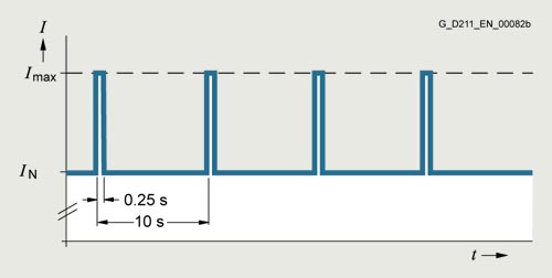
Duty cycle with previous load
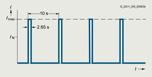
Duty cycle without previous load
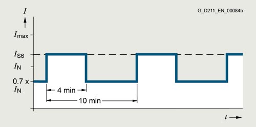
S6 duty cycle with previous load with a duty cycle duration of 600 s
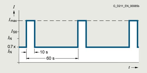
S6 duty cycle with previous load with a duty cycle duration of 60 s
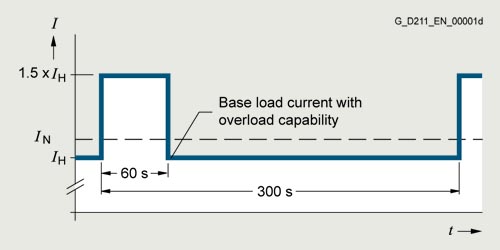
Duty cycle with 60 s overload with a duty cycle duration of 300 s
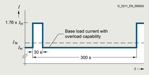
Duty cycle with 30 s overload with a duty cycle duration of 300 s
Motor Modules in booksize format D type, 3 A to 30 A
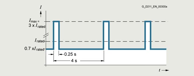
Peak current duty cycle with previous load (300 % overload)
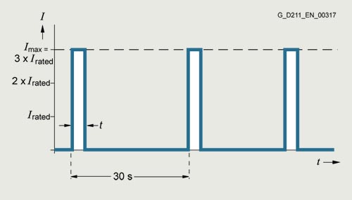
Peak current duty cycle without previous load (300 % overload)
Single Motor Module |
Time t at Imax |
|---|---|
3 A |
0.5 s |
5 A |
0.5 s |
9 A |
0.5 s |
18 A |
1.25 s |
24 A |
1.25 s |
30 A |
3 s |
Note:
The duty cycle shown above is not permissible for a pulse frequency of 16 kHz. The current must be derated for a pulse frequency of 8 kHz.
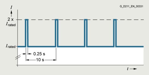
Duty cycle with previous load
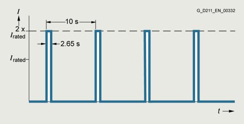
Duty cycle without previous load
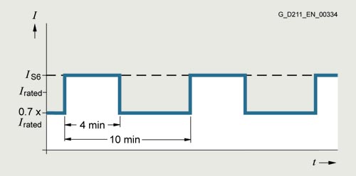
S6 duty cycle with previous load with a duty cycle duration of 600 s
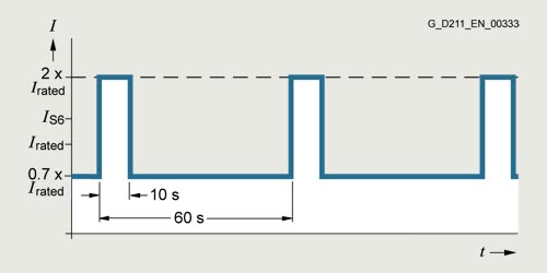
S6 duty cycle with previous load with a duty cycle duration of 60 s
Duty cycle with 60 s overload with a duty cycle duration of 300 s
Duty cycle with 30 s overload with a duty cycle duration of 300 s
Derating characteristics
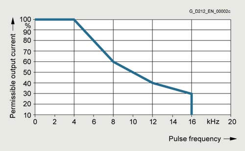
Output current as a function of pulse frequency (Single Motor Modules, 3 A to 132 A)
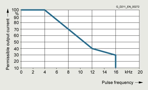
Output current as a function of pulse frequency (Single Motor Modules, 200 A)
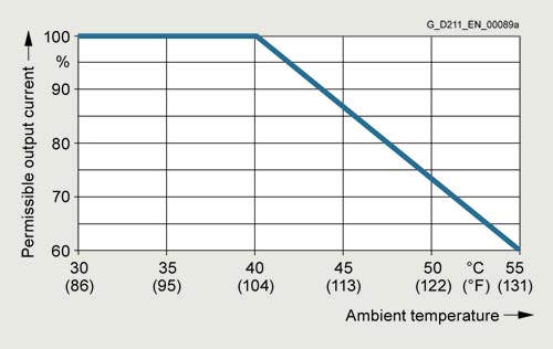
Output current as a function of ambient temperature
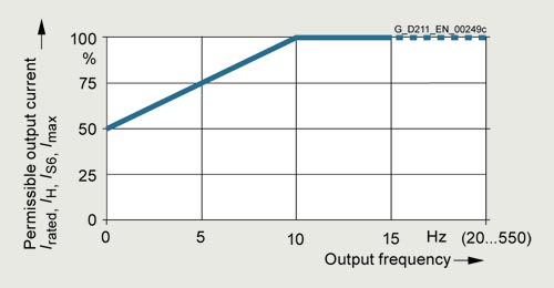
Output current as a function of output frequency (Single Motor Modules in booksize format, 85 A to 200 A)
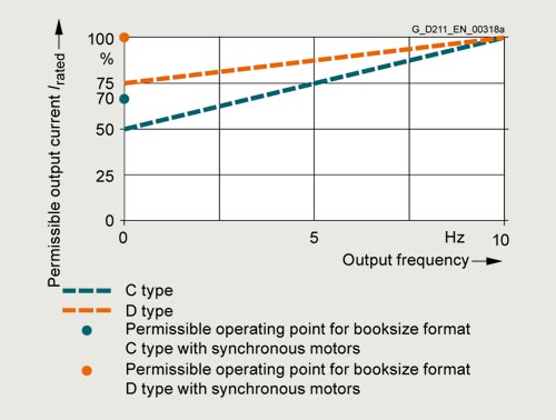
Output current at low output frequencies (Single Motor Modules in booksize format C/D types, 3 A to 60 A)
Installation altitude
- >1000 ... 4000 m (3281 ... 13124 ft) above sea level
- Reduction of the output current by 10 % per 1000 m (3281 ft), or
- Reduction of the ambient temperature by 5 °C (9 °F) per 1000 m (3281 ft)
- >2000 ... 4000 m (6562 ... 13124 ft) above sea level
- Operation on line supply systems with grounded neutral point, or
- Operation with an isolating transformer with secondary grounded neutral point