






















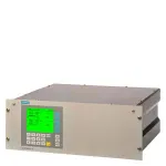
Обзор
ULTRAMAT 6 одно- или двухканальный высокоселективный аналитический прибор с NDIR двулучевым детектором для анализа смеси газов, полосы поглощения которых находятся в инфракрасном диапазоне спектра между 2 и 9 мкм, например, CO, CO2, NO и SO2, NH3, H2O, а так же CH4 и другие углеводороды
Особенности
High selectivity with double-layer detector and optical coupler
- Reliable measurements even in complex gas mixtures
Low detection limits
- Measurements with low concentrations
Corrosion-resistant materials in gas path (option)
- Measurement possible in highly corrosive sample gases
Analyzer cells can be cleaned as required on site
- Cost savings due to reuse after contamination
Electronics and physics: gas-tight isolation, purging is possible, IP65
- Long service life even in harsh environments
Heated versions (option)
- Use also in presence of gases condensing at low temperature
Ex(p) for Zones 1 and 2 (in accordance with to ATEX 2G and ATEX 3G)
Область применения
- Measurement for boiler control in combustion plants
- Emission measurements in combustion plants
- Warning equipment
- Process gas concentrations in chemical plants
- Trace measurements in pure gas processes
- Environmental protection
- TLV (Threshold Limit Value) monitoring at the workplace
- Quality monitoring
- Ex versions for analyzing flammable and non-flammable gases or vapors for use in hazardous areas
Special versions
Special applications
Besides the standard combinations, special applications concerning material in the gas path, material in the sample chambers (e.g. Titan, Hastelloy C22) and measured components are also available on request
Performance-tested version / QAL
For measurements of CO, NO, SO2 and O2 according to sections 13 and 27 of the German Federal Immission Protection Regulations and TA Luft, performance-tested versions according to EN 15267 are available.
Certified measuring range:
- 1-component analyzer
CO: 0 to 75 mg/m³; 0 to 10 000 mg/m³
NO: 0 to 100 mg/m3; 0 to 10 000 mg/m³
SO2: 0 to 75 mg/m3; 0 to 1 500 mg/m³ - O2: 0 to 5 vol.%; 0 to 25 vol.%
In addition, performance-tested versions of the ULTRAMAT 6 meet the requirements set forth in EN 14956 and QAL1 according to EN 14181. Conformity of the analyzers with both standards is TÜV-certified.
Determination of the analyzer drift according to EN 14181 (QAL3) can be carried out manually or also with a PC using the SIPROM GA maintenance and servicing software. In addition, selected manufacturers of emission evaluation computers offer the possibility for downloading the drift data via the analyzer's serial interface and to automatically record and process it in the evaluation computer.
Flow-type reference cell
- The flow through the reference cell should be adapted to the sample gas flow
- The gas supply of the reduced flow-type reference cell should have a primary pressure of 3 000 to 5 000 hPa (abs.). The flow is then automatically regulated at approximately 8 ml/min using a restrictor
Дизайн
19" rack unit
- 19" rack unit with 4 U for installation
- In hinged frame
- In cabinets with or without telescopic rails
- Front plate can be swung down for servicing purposes (laptop connection)
- Internal gas paths: hose made of FKM (Viton) or pipe made of titanium or stainless steel
- Gas connections for sample gas inlet and outlet: pipe diameter 6 mm or 1/4"
- Flow indicator for sample gas on front plate (option)
- Pressure switch in sample gas path for flow monitoring (option)
Field device
- Two-door enclosure with gas-tight separation of the electronics modules from parts conveying gas
- Individually purgeable enclosure halves
- Parts in contact with sample gas can be heated up to 65 °C (option)
- Gas path: hose made of FKM (Viton) or pipe made of titanium or stainless steel (further materials possible as special applications)
- Gas connections for sample gas inlet and outlet: pipe union for pipe diameter 6 mm or 1/4"
- Purging gas connections: pipe diameter 10 mm or 3/8"
Display and operator panel
- Large LCD panel for simultaneous display of:
- Measured value (digital and analog displays)
- Status bar
- Measuring ranges
- Contrast of LCD panel adjustable using menu
- Washable membrane keyboard with five softkeys
- Menu-driven operation for parameterization, test functions, adjustment
- User help in plain text
- Graphic display of concentration trend; programmable time intervals
- Bilingual operating software:
German/English, English/Spanish, French/English, Italian/English, Spanish/English
Inputs and outputs
- One analog output per medium (from 0, 2, 4 to 20 mA; NAMUR parameterizable)
- Two analog inputs freely configurable (e.g. correction of cross-interference or external pressure sensor)
- Six digital inputs freely configurable (e.g. for measurement range switchover, processing of external signals from sample preparation)
- Six relay outputs freely configurable e.g. for fault, maintenance demanded, limit alarm, external solenoid valves
- Expandable with eight additional digital inputs and eight additional relay outputs e.g. for autocalibration with up to four calibration gases
Communication
RS 485 present in the basic unit (connection at the rear; for the rack unit also behind the front plate).
Options
- RS 485/RS 232 converter
- RS 485/Ethernet converter
- RS 485/USB converter
- Connection to networks via PROFIBUS DP/PA interface
- SIPROM GA software as the service and maintenance tool
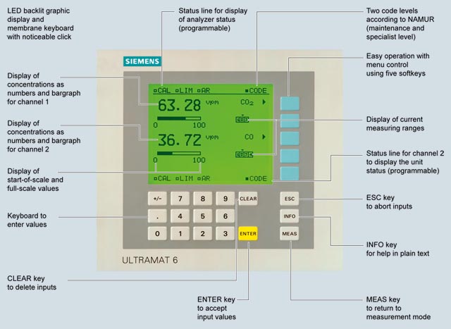
ULTRAMAT 6, membrane keyboard and graphic display
Designs – Parts wetted by sample gas, standard
Gas path |
19" rack unit |
Field device |
Field device Ex |
|
|---|---|---|---|---|
With hoses |
Bushing |
Stainless steel, mat. No. 1.4571 |
Stainless steel, mat. No. 1.4571 |
- |
Hose |
FKM (e.g. Viton) |
FKM (e.g. Viton) |
- |
|
Sample chamber: |
||||
|
Aluminum |
Aluminum |
- |
|
|
Aluminum |
Aluminum |
- |
|
|
Stainless steel, mat. No. 1.4571 O-ring: FKM (e.g. Viton) or FFKM (Kalrez) |
Stainless steel, mat. No. 1.4571 O-ring: FKM (e.g. Viton) or FFKM (Kalrez) |
- |
|
|
CaF2, adhesive: E353, O-ring: FKM (e.g. Viton) or FFKM (Kalrez) |
CaF2, adhesive: E353, O-ring: FKM (e.g. Viton) or FFKM (Kalrez) |
- |
|
With pipes |
Bushing |
Titanium |
Titanium |
Titanium |
Pipe |
Titanium O-ring: FKM (e.g. Viton) or FFKM (Kalrez) |
Titanium O-ring: FKM (e.g. Viton) or FFKM (Kalrez) |
Titanium O-ring: FKM (e.g. Viton) or FFKM (Kalrez) |
|
Sample chamber: |
||||
|
Aluminum |
Aluminum |
Aluminum |
|
|
Tantalum (only for cell length 20 … 180 mm) |
Tantalum (only for cell length 20 … 180 mm) |
Tantalum (only for cell length 20 … 180 mm) |
|
|
CaF2, adhesive: E353, O-ring: FKM (e.g. Viton) or FFKM (Kalrez) |
CaF2, adhesive: E353, O-ring: FKM (e.g. Viton) or FFKM (Kalrez) |
CaF2, adhesive: E353, O-ring: FKM (e.g. Viton) or FFKM (Kalrez) |
|
With pipes |
Bushing |
Stainless steel, mat. No. 1.4571 |
Stainless steel, mat. No. 1.4571 |
Stainless steel, mat. No. 1.4571 |
Pipe |
Stainless steel, mat. No. 1.4571 O-ring: FKM (e.g. Viton) or FFKM (Kalrez) |
Stainless steel, mat. No. 1.4571 O-ring: FKM (e.g. Viton) or FFKM (Kalrez) |
Stainless steel, mat. No. 1.4571 O-ring: FKM (e.g. Viton) or FFKM (Kalrez) |
|
Sample chamber: |
||||
|
Aluminum |
Aluminum |
Aluminum |
|
|
Aluminum or tantalum (tantalum only for cell length 20 … 180 mm) |
Aluminum or tantalum (tantalum only for cell length 20 … 180 mm) |
Aluminum or tantalum (tantalum only for cell length 20 … 180 mm) |
|
|
CaF2, adhesive: E353, O-ring: FKM (e.g. Viton) or FFKM (Kalrez) |
CaF2, adhesive: E353, O-ring: FKM (e.g. Viton) or FFKM (Kalrez) |
CaF2, adhesive: E353, O-ring: FKM (e.g. Viton) or FFKM (Kalrez) |
|
Options
Gas path |
19" rack unit |
Field device |
Field device Ex |
|
|---|---|---|---|---|
Flow indicator |
Measuring tube |
Duran glass |
- |
- |
Variable area |
Duran glass |
- |
- |
|
Suspension boundary |
PTFE (Teflon) |
- |
- |
|
Angle units |
FKM (e.g. Viton) |
- |
- |
|
Pressure switch |
Diaphragm |
FKM (e.g. Viton) |
- |
- |
Enclosure |
PA 6.3T |
- |
- |
|
Versions – Parts wetted by sample gas, special applications (examples)
Gas path |
19" rack unit |
Field device |
Field device Ex |
|
|---|---|---|---|---|
With pipes |
Bushing |
e.g. Hastelloy C22 |
e.g. Hastelloy C22 |
e.g. Hastelloy C22 |
Pipe |
e.g. Hastelloy C22 O-ring: FKM (e.g. Viton) or FFKM (Kalrez) |
e.g. Hastelloy C22 O-ring: FKM (e.g. Viton) or FFKM (Kalrez) |
e.g. Hastelloy C22 O-ring: FKM (e.g. Viton) or FFKM (Kalrez) |
|
Sample chamber: |
||||
|
e.g. Hastelloy C22 |
e.g. Hastelloy C22 |
e.g. Hastelloy C22 |
|
|
CaF2, without adhesive O-ring: FKM (e.g. Viton) or FFKM (Kalrez) |
CaF2, without adhesive O-ring: FKM (e.g. Viton) or FFKM (Kalrez) |
CaF2, without adhesive O-ring: FKM (e.g. Viton) or FFKM (Kalrez) |
|
Gas path (19" rack unit)
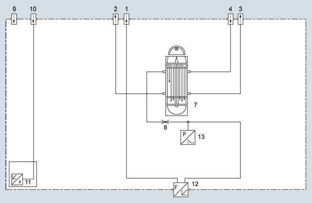
Gas path ULTRAMAT 6, single-channel unit, 19" rack unit, with flow-type reference cell (option)
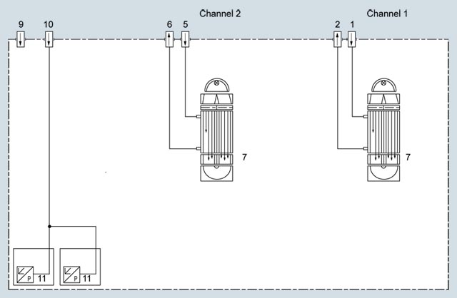
Gas path ULTRAMAT 6, dual-channel unit, 19" rack unit
Legend for the figures "Gas path (19" rack unit)" | |||
|---|---|---|---|
1 |
Sample gas inlet channel 1 |
8 |
Restrictor |
2 |
Sample gas outlet channel 1 |
9 |
Purging gas inlet |
3 |
Reference gas outlet (option) |
10 |
Connection of atmospheric pressure sensor |
4 |
Reference gas inlet (option) |
11 |
Atmospheric pressure sensor |
5 |
Sample gas inlet channel 2 |
12 |
Flow indicator in sample gas path (option) |
6 |
Sample gas outlet channel 2 |
13 |
Pressure switch in sample gas path (option) |
7 |
IR physical system |
||
Gas path (field device)
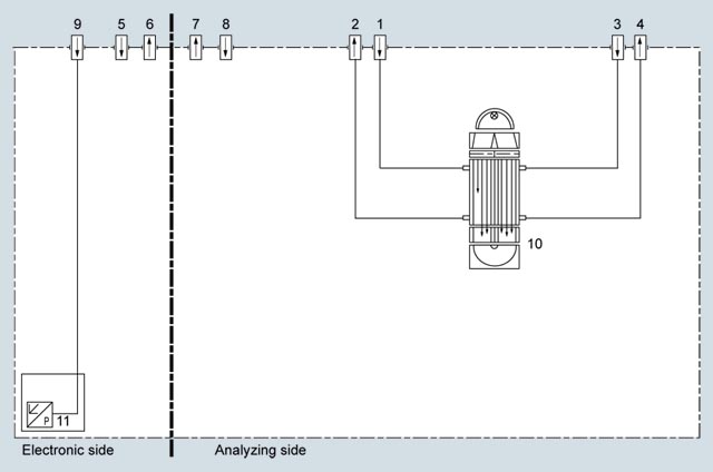
Gas path ULTRAMAT 6, field device, with flow-type reference cell (option)
Legend for figure "Gas path (field device)" | |||
|---|---|---|---|
1 |
Sample gas inlet |
7 |
Purging gas outlet (analyzer side) |
2 |
Sample gas outlet |
8 |
Purging gas inlet (analyzer side) |
3 |
Reference gas inlet (option) |
9 |
Connection of atmospheric pressure sensor |
4 |
Reference gas outlet (option) |
10 |
IR physical system |
5 |
Purging gas inlet (electronics side) |
11 |
Atmospheric pressure sensor |
6 |
Purging gas outlet (electronics side) |
||
Способ действия
The ULTRAMAT 6 gas analyzer operates according to the infrared two-beam modulated light principle with double-layer detector and optical coupler.
The measuring principle is based on the molecule-specific absorption of bands of infrared radiation. The absorbed wavelengths are characteristic to the individual gases, but may partially overlap. This results in cross-sensitivities which are reduced to a minimum in the ULTRAMAT 6 gas analyzers by the following measures:
- Gas-filled filter cell (beam divider)
- Double-layer detector with optical coupler
- Optical filters if necessary
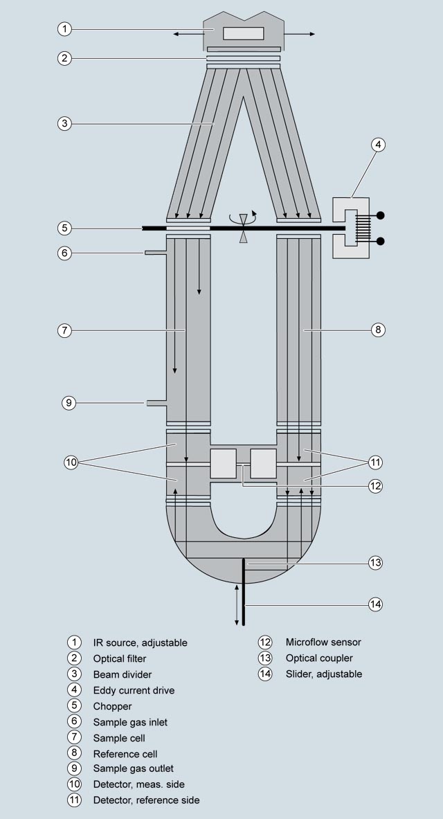
The figure shows the measuring principle. An IR source (1) which is heated to approx. 700 °C and which can be shifted to balance the system is divided by the beam divider (3) into two equal beams (sample and reference beams). The beam divider also acts as a filter cell.
The reference beam passes through a reference cell (8) filled with N2 (a non-infrared-active gas) and reaches the right-hand side of the detector chamber (11) practically unattenuated. The sample beam passes through the sample chamber (7) through which the sample gas flows and reaches the left-hand side of the detector (10) attenuated to a lesser or greater extent depending on the concentration of the sample gas. The detector chamber is filled with a defined concentration of the gas component to be measured.
The detector is designed as a double-layer detector. The center of the absorption band is preferentially absorbed in the upper detector layer, the edges of the band are absorbed to approximately the same extent in the upper and lower layers. The upper and lower detector layers are connected together via the microflow sensor (12). This coupling means that the spectral sensitivity has a very narrow band.
The optical coupler (13) lengthens the lower detector chamber layer optically. The infrared absorption in the second detector chamber layer is varied by changing the slider position (14). It is thus possible to individually minimize the influence of interfering components.
A chopper (5) rotates between the beam divider and the sample chamber and interrupts the two beams alternately and periodically. If absorption takes place in the sample chamber, a pulsating flow is generated between the two detector levels which is converted by the microflow sensor (12) into an electric signal.
The microflow sensor consists of two nickel-plated grids heated to approximately 120 °C, which, along with two supplementary resistors, form a Wheatstone bridge. The pulsating flow together with the dense arrangement of the Ni grids causes a change in resistance. This leads to an offset in the bridge, which is dependent on the concentration of the sample gas.
Notes
The sample gases must be fed into the analyzers free of dust. Condensation in the sample chambers must be prevented. Therefore, the use of gas modified for the measuring task is necessary in most application cases.
As far as possible, the ambient air of the analyzer unit should not have a large concentration of the gas components to be measured.
Flow-type reference cells with reduced flow must not be operated with flammable or toxic gases.
Flow-type reference cells with reduced flow and an O2 content > 70% may only be used together with Y02 ("Clean for O2").
Channels with electronically suppressed zero point only differ from the standard version in the measuring range parameterization.
Physically suppressed zeros can be provided as a special application.
ULTRAMAT 6, principle of operation
Функции
Main features
- Dimension of measured value freely selectable (e.g. vpm, mg/m3)
- Four freely parameterizable measuring ranges per component
- Measuring ranges with suppressed zero point possible
- Measuring range identification
- Electrically isolated measured value output 0/2/4 up to 20 mA per component
- Automatic or manual measuring range switchover selectable; remote switching is also possible
- Differential measuring ranges with flow-type reference cell
- Storage of measured values possible during calibration
- Wide range of selectable time constants (static/dynamic noise damping); i.e. the response time of the device or component can be adapted to the respective measuring task
- Short response time
- Low long-term drift
- Measuring point switchover for up to 6 measuring points (parameterizable)
- Measuring point identification
- Monitoring of sample gas flow (option)
- Internal pressure sensor for correction of variations in atmospheric pressure in the range 700 to 1 200 hPa absolute
- External pressure sensor can be connected for correction of variations in the process gas pressure in the range 700 to 1 500 hPa absolute (option)
- Two input levels with separate authorization codes to prevent unintentional and unauthorized operator intervention
- Automatic measuring range calibration parameterizable
- Simple handling using a numerical membrane keyboard and operator prompting
- Operation based on NAMUR recommendation
- Custom-made device designs, such as:
- Customer acceptance
- TAG plates
- Clean for O2 service (specially cleaned gas path)
- Easy device replacement since electrical connections can be simply disconnected from the device
- Sample chambers for use in presence of highly corrosive sample gases, e.g. tantalum layer or sample chamber made of Hastelloy C22 (special application)
Additional features, dual-channel version
- Separate design of physical unit, electronics, inputs/outputs and power supply for each channel
- Display and operation via common LCD panel and keyboard
- Measurement channels 1 and 2 can be converted to series connection (linking of gas connections from channel 1 to channel 2 at the rear of the device)