


















Технические данные
General technical specifications
Unless clearly specified otherwise, the following technical data are valid for all the following components of the air-cooled SINAMICS S120 drive system in chassis format.
Electrical specifications | |||
|---|---|---|---|
Line voltages |
380 ... 480 V 3 AC ±10 % (-15 % <1 min) 500 ... 690 V 3 AC ±10 % (-15 % <1 min) |
||
Line supply types |
Grounded TN/TT systems and non-grounded IT systems |
||
Line frequency |
47 ... 63 Hz |
||
Overvoltage category |
III acc. to EN 61800-5-1 |
||
Electronics power supply |
24 V DC, -15 % +20 % |
||
|
Rated short-circuit current per IEC, in conjunction with the specified fuses or circuit breakers |
|||
|
65 kA |
||
|
84 kA |
||
|
170 kA |
||
|
200 kA |
||
|
Rated short-circuit current SCCR according to UL508C (up to 600 V), in conjunction with the specified fuses or circuit breakers |
|||
|
65 kA |
||
|
84 kA |
||
|
170 kA |
||
|
200 kA |
||
Control method |
Vector/Servo control with and without encoder or V/f control |
||
Fixed speeds |
15 fixed speeds plus 1 minimum speed, parameterizable |
||
Skippable speed ranges |
4, parameterizable |
||
Setpoint resolution |
0.001 r/min digital (14 bits + sign) |
||
Braking operation |
With Active Line Modules and Smart Line Modules, four-quadrant operation as standard (energy recovery). |
||
Mechanical specifications | |||
Degree of protection |
IP00 or IP20 depending on type |
||
Protection class |
I acc. to EN 61800‑5‑1 |
||
Touch protection |
EN 50274/DGUV regulation 3 when used as intended |
||
Cooling method |
Forced air cooling AF according to EN 60146 |
||
Ambient conditions |
Storage 1) |
Transport 1) |
Operation |
Ambient temperature |
-25 ... +55 °C (-13 ... 131 °F) Class 1K4 |
-25 ... +70 °C (-13 ... +158 °F) Class 2K4 |
Line-side components, Power Modules, Line Modules and Motor Modules: Control Units, supplementary system components, and Sensor Modules: DC link components and motor-side components: |
|
Relative humidity Condensation, splashwater, and ice formation not permitted (EN 60204, Part 1) |
5 ... 95 % Class 1K4 |
5 ... 95 % at 40 °C (104 °F) Class 2K3 |
5 ... 95 % Class 3K3 |
Environmental class/harmful chemical substances |
Class 1C2 |
Class 2C2 |
Class 3C2 |
Organic/biological influences |
Class 1B1 |
Class 2B1 |
Class 3B1 |
Mechanically active substances |
Class 1S1 |
Class 2S1 |
Class 3S1 |
Degree of pollution |
2 acc. to EN 61800‑5‑1 |
||
Installation altitude |
Up to 2000 m (6562 ft) above sea level without derating |
||
Mechanical stability |
Storage 1) |
Transport 1) |
Operation |
Vibratory load |
– |
Class 2M2 |
Test values
|
Shock load |
– |
Class 2M2 |
Test values |
Compliance with standards | |||
Conformances/certificates of suitability, according to |
CE (EMC Directive No. 2014/30/EU, Low Voltage Directive No. 2014/35/EU, and Machinery Directive 2006/42/EC for functional safety) |
||
Radio interference suppression |
SINAMICS S120 chassis format units are not designed for connection to the public grid (first environment). Radio interference suppression is compliant with the EMC product standard for variable-speed drives EN 61800‑3, "second environment" (industrial line supplies). EMC disturbances can occur when connected to the public grid. However, if additional measures are taken (e.g. → line filter), it can also be operated in the "first environment". For further information, see section Engineering information. |
||
1) In transport packaging.
Deviations from the specified class are underlined.
Характеристика
Derating data, chassis format
Air-cooled SINAMICS G120 chassis format units and the associated system components are rated for an ambient temperature of 40 °C and installation altitudes up to 2000 m above sea level.
At ambient temperatures > 40 °C, the output current must be reduced. Ambient temperatures above 55 °C are not permissible.
At installation altitudes > 2000 m above sea level, it must be taken into account that the air pressure, and therefore air density, decreases as the height increases. As a consequence, the cooling efficiency and the insulation capacity of the air also decrease.
Due to the reduced cooling efficiency, it is necessary, on the one hand, to reduce the ambient temperature and on the other hand, to reduce the heat loss in the built-in unit by reducing the output current, whereby ambient temperatures lower than 40 °C may be offset to compensate.
The following table lists the permissible output currents depending on the installation altitude and ambient temperature. The specified values already include a permitted compensation in respect of installation altitude and ambient temperatures < 40 °C (temperature at the air intake of the built-in unit).
The values apply under the precondition that a cooling air flow through the devices is guaranteed as specified in the technical specifications.
As additional measure for installation altitudes from 2000 m up to 5000 m, an isolating transformer is required in order to reduce transient overvoltages according to EN 60664‑1.
For additional information, please refer to the SINAMICS Low Voltage Engineering Manual.
Current-derating factors for SINAMICS S120 chassis units as a function of the ambient/air intake temperature and the installation altitude
Installation altitude above sea level |
Current derating factor (as a percentage of the rated current) |
|||||||
|---|---|---|---|---|---|---|---|---|
m (ft) |
20 °C (68 °F) |
25 °C (77 °F) |
30 °C (86 °F) |
35 °C (95 °F) |
40 °C (104 °F) |
45 °C (113 °F) |
50 °C (122 °F) |
55 °C (131 °F) |
0 ... 2000 (0 ... 6562) |
100 % |
100 % |
100 % |
100 % |
100 % |
93.3 % |
86.7 % |
80 % |
2001 ... 2500 (6565 ... 8202) |
100 % |
100 % |
100 % |
100 % |
96.3 % |
|||
2501 ... 3000 (8205 ... 9843) |
100 % |
100 % |
100 % |
98.7 % |
||||
3001 ... 3500 (9846 ... 11483) |
100 % |
100 % |
100 % |
|||||
3501 ... 4000 (11486 ... 13123) |
100 % |
100 % |
96.3 % |
|||||
4001 ... 4500 (13127 ... 14764) |
100 % |
97.5 % |
||||||
4501 ... 5000 (14767 ... 16404) |
98.2 % |
|||||||
Current derating for Power Modules and Motor Modules in chassis format as a function of the pulse frequency
To reduce motor noise or to increase output frequency, the pulse frequency can be increased relative to the factory setting (1.25 kHz or 2 kHz). When the pulse frequency is increased, the derating factor of the output current must be taken into account. This derating factor must be applied to the currents specified in the technical specifications.
For additional information, please refer to the SINAMICS Low Voltage Engineering Manual.
The following table lists the rated output currents of the SINAMICS S120 Power Modules and Motor Modules with pulse frequency set in the factory as well as the current derating factors (permissible output currents referred to the rated output current) for higher pulse frequencies.
Derating factor of the output current as a function of the pulse frequency for units with a rated pulse frequency of 2 kHz
Power Module |
Type rating |
Output current |
Derating factor at pulse frequency |
||||
|---|---|---|---|---|---|---|---|
6SL3310-... |
kW |
A |
2.5 kHz |
4 kHz |
5 kHz |
7.5 kHz |
8 kHz |
380 ... 480 V 3 AC | |||||||
1TE32-1AA3 |
110 |
210 |
95 % |
82 % |
74 % |
54 % |
50 % |
1TE32-6AA3 |
132 |
260 |
95 % |
83 % |
74 % |
54 % |
50 % |
1TE33-1AA3 |
160 |
310 |
97 % |
88 % |
78 % |
54 % |
50 % |
1TE33-8AA3 |
200 |
380 |
96 % |
87 % |
77 % |
54 % |
50 % |
1TE35-0AA3 |
250 |
490 |
94 % |
78 % |
71 % |
53 % |
50 % |
1TE41-4AS3 |
800 |
1330 |
88 % |
55 % |
- |
- |
- |
Derating factor of the output current as a function of the pulse frequency for units with a rated pulse frequency of 1.25 kHz
Motor Module |
Type rating |
Output current |
Derating factor at pulse frequency |
|||||
|---|---|---|---|---|---|---|---|---|
6SL3320-... |
kW |
A |
2 kHz |
2.5 kHz |
4 kHz |
5 kHz |
7.5 kHz |
8 kHz |
380 ... 480 V 3 AC |
||||||||
1TE36-1AA3 |
315 |
605 |
83 % |
72 % |
64 % |
60 % |
40 % |
36% |
1TE37-5AA3 |
400 |
745 |
83 % |
72 % |
64 % |
60 % |
40 % |
36% |
1TE38-4AA3 |
450 |
840 |
87 % |
79 % |
64 % |
55 % |
40 % |
37 % |
1TE41-0AA3 |
560 |
985 |
92 % |
87 % |
70 % |
60 % |
50 % |
47 % |
1TE41-2AA3 |
710 |
1260 |
92 % |
87 % |
70 % |
60 % |
50 % |
47 % |
1TE41-4AA3 |
800 |
1405 |
97 % |
95 % |
74 % |
60 % |
50 % |
47 % |
500 ... 690 V 3 AC |
||||||||
1TG28-5AA3 |
75 |
85 |
93 % |
89 % |
71 % |
60 % |
40 % |
- |
1TG31-0AA3 |
90 |
100 |
92 % |
88 % |
71 % |
60 % |
40 % |
- |
1TG31-2AA3 |
110 |
120 |
92 % |
88 % |
71 % |
60 % |
40 % |
- |
1TG31-5AA3 |
132 |
150 |
90 % |
84 % |
66 % |
55 % |
35 % |
- |
1TG31-8AA3 |
160 |
175 |
92 % |
87 % |
70 % |
60 % |
40 % |
- |
1TG32-2AA3 |
200 |
215 |
92 % |
87 % |
70 % |
60 % |
40 % |
- |
1TG32-6AA3 |
250 |
260 |
92 % |
88 % |
71 % |
60 % |
40 % |
- |
1TG33-3AA3 |
315 |
330 |
89 % |
82 % |
65 % |
55 % |
40 % |
- |
1TG34-1AA3 |
400 |
410 |
89 % |
82 % |
65 % |
55 % |
35 % |
- |
1TG34-7AA3 |
450 |
465 |
92 % |
87 % |
67 % |
55 % |
35 % |
- |
1TG35-8AA3 |
560 |
575 |
91 % |
85 % |
64 % |
50 % |
35 % |
- |
1TG37-4AA3 |
710 |
735 |
87 % |
79 % |
64 % |
55 % |
35 % |
- |
1TG38-1AA3 |
800 |
810 |
97 % |
95 % |
71 % |
55 % |
35 % |
- |
1TG38-8AA3 |
900 |
910 |
92 % |
87 % |
67 % |
55 % |
33 % |
- |
1TG41-0AA3 |
1000 |
1025 |
91 % |
86 % |
64 % |
50 % |
30 % |
- |
1TG41-3AA3 |
1200 |
1270 |
87 % |
79 % |
55 % |
40 % |
25 % |
- |
Maximum output frequencies achieved by increasing the pulse frequency
The adjustable pulse frequencies – and therefore the output frequencies that can be achieved with the factory-set current controller clock cycles – are listed below.
Current controller clock cycle |
Adjustable pulse frequency |
Max. achievable output frequency fA |
||
|---|---|---|---|---|
V/f mode |
Vector mode |
Servo mode |
||
250 µs 1) |
2 kHz |
166 Hz |
166 Hz |
333 Hz |
4 kHz |
333 Hz |
333 Hz |
550 Hz 3) |
|
8 kHz |
550 Hz 3) |
480 Hz |
550 Hz 3) |
|
400 µs 2) |
1.25 kHz |
104 Hz |
104 Hz |
– |
2.5 kHz |
208 Hz |
208 Hz |
– |
|
5.0 kHz |
416 Hz |
300 Hz |
– |
|
7.5 kHz |
550 Hz 3) |
300 Hz |
– |
|
1) As factory setting, the following devices have a current controller clock cycle of 250 µs - and a pulse frequency of 2 kHz: - 3 AC 380 ... 480 V: ≤250 kW / 490 A, 6SL3320-1TE41-4AS3
2) As factory setting, the following devices have a current controller clock cycle of 400 µs and a pulse frequency of 1.25 kHz: - 380 ... 480 V 3 AC: ≥315 kW / 605 A, except 6SL3320-1TE41-4AS3, - 500 ... 690 V 3 AC: All power ratings
3) With the "High output frequencies" license, which can be ordered as option J01 on the CompactFlash card for SINAMICS S120, the maximum output frequency is increased up to 650 Hz. For more information, see
Overload capability
SINAMICS S120 built-in units have an overload reserve, e.g. to handle breakaway torques. If larger surge loads occur, this must be taken into account in the configuration. For drives with overload requirements, the appropriate base load current must, therefore, be used as a basis for the required load.
The permissible overload levels are valid under the prerequisite that the drive units are operated with their base-load current before and after the overload condition based on a duty cycle duration of 300 s.
Another precondition is that the Power Modules or the Motor Modules are operated at their factory-set pulse frequency at output frequencies > 10 Hz.
For temporary, periodic duty cycles with high variations of load within the duty cycle, the relevant sections of the SINAMICS Low Voltage Engineering Manual must be observed.
Power Modules and Motor Modules
The base load current for a low overload IL is based on a duty cycle of 110 % for 60 s or 150 % for 10 s.
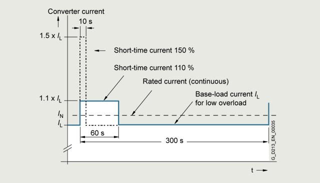
Low overload
The base load current for a high overload IH is based on a duty cycle of 150 % for 60 s or 160 % for 10 s.
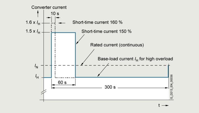
High overload
Line Modules
The base-load current for a high overload IH DC is the basis for a duty cycle of 150 % for 60 s or Imax DC for 5 s.
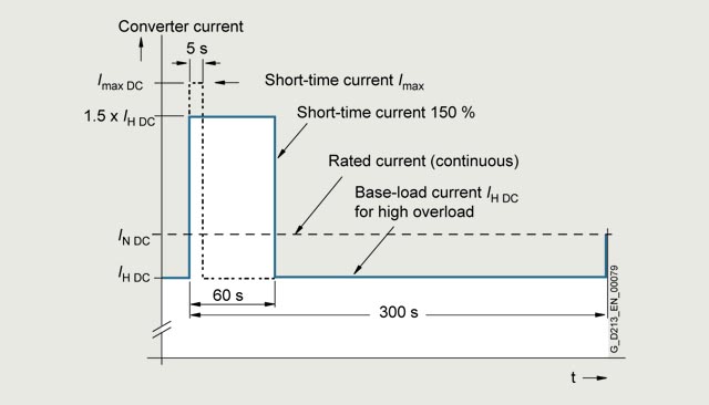
High overload