


















Обзор
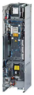
Basic Line Modules are available for applications in which no energy is returned to the supply or where the energy exchange between motor and generator axes takes place in the DC link. Basic Line Modules are designed for connection to grounded TN/TT and non-grounded IT supply systems.
The Basic Line Modules are available in different frame sizes. With frame sizes FB and GB, a fully controlled thyristor bridge is used to pre-charge the Basic Line Modules and connected Motor Modules. The thyristors normally operate with a trigger delay angle of 0°.
Basic Line Modules, frame size GD for 900 kW (400 V) or 1500 kW (690 V) include a diode bridge, and the DC link is pre-charged via a separate line-side pre-charging circuit.
A Braking Module of the appropriate frame size can be integrated into a Basic Line Module in order to permit, in conjunction with an external braking resistor, regenerative operation of the drive system (see section System components → DC link components).
Дизайн
The Basic Line Modules have the following interfaces as standard:
- 1 line supply connection
- 1 connection for the 24 V DC electronics power supply
- 1 DC link connection (DCP, DCN) for supplying the connected Motor Modules
- 1 DC link connection (DCPA, DCNA) for connecting a Braking Module
- 3 DRIVE‑CLiQ sockets
- 1 temperature sensor input for KTY84‑130, Pt1000 or PTC (Pt1000 can be used from firmware V4.7 HF17 and higher)
- 1 PE/protective conductor connection
The status of the Basic Line Modules is indicated via three LEDs.
The scope of supply of the Basic Line Modules includes:
- DRIVE‑CLiQ cable to connect to a Control Unit
- DRIVE‑CLiQ cable to connect the Control Unit to the first Motor Module
- 1 set of warning labels in 30 languages
(BG, CN, CZ, DE, DK, EE, ES, FI, FR, GB, GR, HU, IE, IS, IT, JP, KR, LT, LV, MT, NL, NO, PL, PT, RO, RU, SE, SI, SK, TR)
Pre-charging circuit for the Basic Line Modules, frame size GD
Unlike Basic Line Modules in frame sizes FB and GB, a Basic Line Module in frame size GD requires a separate precharging circuit. The pre-charging circuit components must be ordered separately.
During startup, the pre-charging circuit ensures that the DC link capacitors of the Basic Line Module and the connected Motor Modules are pre-charged with current limiting. After pre-charging has been completed, the circuit breaker is closed and the pre-charging circuit bypassed; the Basic Line Module is then directly connected to the line supply.
The pre-charging circuit comprises a pre-charging contactor and pre-charging resistors; the circuit must be protected against overcurrent using suitable protection measures. To increase the permissible DC link capacitance, the pre-charging resistors can also be connected in parallel in each phase.
More information on the pre-charging circuit is to be found in the SINAMICS Low Voltage Engineering Manual.
For components for the pre-charging circuit and for recommended line-side system components, see System components.
Интеграция
The Basic Line Modules communicate with the higher-level control module via DRIVE-CLiQ. The control module in this case can be a CU320-2 Control Unit. An external 24 V DC power supply is required to operate Basic Line Modules.
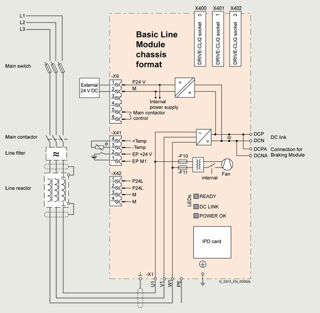
Connection example for Basic Line Module, frame sizes FB, GB
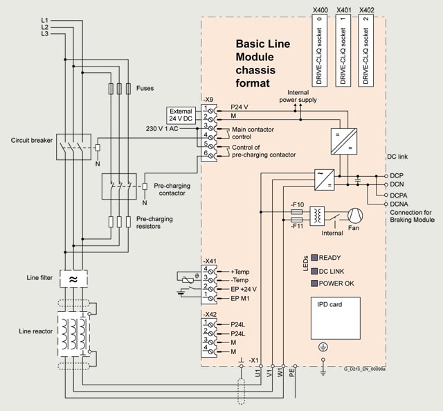
Connection example, Basic Line Module, frame size GD
Технические данные
General technical specifications
Electrical specifications | |
|---|---|
|
Line power factor at rated power |
|
|
>0.96 |
|
0.75 ... 0.93 |
Efficiency |
>99 % |
DC link voltage, approx. 1) |
1.35 × line voltage under partial load |
Main contactor control |
|
|
240 V AC, max. 8 A |
1) The DC link voltage is unregulated and load-dependent. For additional information, please refer to the SINAMICS Low Voltage Engineering Manual.
Line voltage 380 ... 480 V 3 AC |
Basic Line Modules |
||||||
|---|---|---|---|---|---|---|---|
6SL3330-1TE34-2AA3 |
6SL3330-1TE35-3AA3 |
6SL3330-1TE38-2AA3 |
6SL3330-1TE41-2AA3 |
6SL3330-1TE41-5AA3 |
6SL3330-1TE41-8AA3 |
||
Rated power |
|||||||
|
kW |
200 |
250 |
400 |
560 |
710 |
900 |
|
kW |
160 |
200 |
315 |
450 |
560 |
705 |
|
hp |
305 |
385 |
615 |
860 |
1090 |
1390 |
|
hp |
245 |
305 |
485 |
690 |
860 |
1090 |
DC link current |
|||||||
|
A |
420 |
530 |
820 |
1200 |
1500 |
1880 |
|
A |
328 |
413 |
640 |
936 |
1170 |
1467 |
|
A |
630 |
795 |
1230 |
1800 |
2250 |
2820 |
Input current |
|||||||
|
A |
365 |
460 |
710 |
1010 |
1265 |
1630 |
|
A |
547 |
690 |
1065 |
1515 |
1897 |
2380 |
• Max. pre-charging current (max. 3 s) |
A |
Internal |
Internal |
Internal |
Internal |
Internal |
308 |
Current demand |
|||||||
|
A |
1.1 |
1.1 |
1.1 |
1.1 |
1.1 |
1.1 |
DC link capacitance |
|||||||
|
μF |
7200 |
9600 |
14600 |
23200 |
29000 |
34800 |
|
μF |
57600 |
76800 |
116800 |
185600 |
232000 |
139200/278400 2) |
Power loss, max. 3) |
|||||||
|
kW |
1.9 |
2.1 |
3.2 |
4.6 |
5.5 |
6.9 |
|
kW |
1.9 |
2.1 |
3.2 |
4.6 |
5.5 |
6.9 |
Cooling air requirement |
m3/s (ft3/s) |
0.17 (6.00) |
0.17 (6.00) |
0.17 (6.00) |
0.36 (12.7) |
0.36 (12.7) |
0.36 (12.7) |
|
Sound pressure level LpA (1 m) at 50/60 Hz |
dB |
66/68 |
66/68 |
66/68 |
71/73 |
71/73 |
71/73 |
|
Line connection U1, V1, W1 |
Flat connector for M10 screw |
Flat connector for M10 screw |
Flat connector for M10 screw |
Flat connector for M12 screw |
Flat connector for M12 screw |
Flat connector for M12 screw |
|
|
mm2 |
2 × 240 |
2 × 240 |
2 × 240 |
6 × 185 |
6 × 185 |
6 × 185 |
|
DC link connection DCP, DCN |
M10 screw |
M10 screw |
M10 screw |
3 × hole for M12 |
3 × hole for M12 |
3 × hole for M12 |
|
|
mm2 |
2 × 240 |
2 × 240 |
2 × 240 |
6 × 185 |
6 × 185 |
6 × 185 |
PE/GND connection |
2 × hole for M10 |
2 × hole for M10 |
2 × hole for M10 |
2 × hole for M12 |
2 × hole for M12 |
2 × hole for M12 |
|
|
mm2 |
2 × 240 |
2 × 240 |
2 × 240 |
4 × 240 |
4 × 240 |
4 × 240 |
Cable length, max. 4) |
|||||||
|
m (ft) |
2600 (8530) |
2600 (8530) |
2600 (8530) |
4000 (13123) |
4000 (13123) |
4800 (15748) |
|
m (ft) |
3900 (12795) |
3900 (12795) |
3900 (12795) |
6000 (19685) |
6000 (19685) |
7200 (23622) |
Degree of protection |
IP00 |
IP00 |
IP00 |
IP00 |
IP00 |
IP00 |
|
Dimensions |
|||||||
|
mm (in) |
310 (12.2) |
310 (12.2) |
310 (12.2) |
310 (12.2) |
310 (12.2) |
310 (12.2) |
|
mm (in) |
1164 (45.8) |
1164 (45.8) |
1164 (45.8) |
1653 (65.1) |
1653 (65.1) |
1653 (65.1) |
|
mm (in) |
352 (13.9) |
352 (13.9) |
352 (13.9) |
550 (21.7) |
550 (21.7) |
550 (21.7) |
Weight, approx. |
kg (lb) |
96 (212) |
96 (212) |
96 (212) |
214 (472) |
214 (472) |
214 (472) |
Frame size |
FB |
FB |
FB |
GB |
GB |
GD |
|
Minimum short-circuit current 5) |
kA |
4.4 |
5.2 |
10 |
12.4 |
18.4 |
18.6 |
1) The base-load current IH DC is the basis for a duty cycle of 150 % for 60 s or Imax DC for 5 s with a duty cycle duration of 300 s.
2) The first value applies for one precharging resistor for each phase, the second value for two precharging resistors connected in parallel for each phase.
3) The specified power loss represents the maximum value at 100 % utilization. The value is lower under normal operating conditions.
4) Total of all motor cables and DC link. Longer cable lengths for specific configurations are available on request. For additional information, please refer to the SINAMICS Low Voltage Engineering Manual.
5) Current required for reliably triggering protective devices.
Line voltage 500 ... 690 V 3 AC |
Basic Line Modules |
||||||
|---|---|---|---|---|---|---|---|
6SL3330-1TG33-0AA3 |
6SL3330-1TG34-3AA3 |
6SL3330-1TG36-8AA3 |
6SL3330-1TG41-1AA3 |
6SL3330-1TG41-4AA3 |
6SL3330-1TG41-8AA3 |
||
Rated power |
|||||||
|
kW |
250 |
355 |
560 |
900 |
1100 |
1500 |
|
kW |
195 |
280 |
440 |
710 |
910 |
1220 |
|
kW |
175 |
250 |
390 |
635 |
810 |
1085 |
|
kW |
165 |
235 |
365 |
595 |
755 |
1015 |
|
hp |
250 |
350 |
600 |
900 |
1250 |
1500 |
|
hp |
200 |
300 |
450 |
800 |
1000 |
1250 |
DC link current |
|||||||
|
A |
300 |
430 |
680 |
1100 |
1400 |
1880 |
|
A |
234 |
335 |
530 |
858 |
1092 |
1467 |
|
A |
450 |
645 |
1020 |
1650 |
2100 |
2820 |
Input current |
|||||||
|
A |
260 |
375 |
575 |
925 |
1180 |
1580 |
|
A |
390 |
563 |
863 |
1388 |
1770 |
2370 |
|
A |
Internal |
Internal |
Internal |
Internal |
Internal |
234 |
Current demand |
|||||||
|
A |
1.1 |
1.1 |
1.1 |
1.1 |
1.1 |
1.1 |
DC link capacitance |
|||||||
|
μF |
3200 |
4800 |
7300 |
11600 |
15470 |
19500 |
|
μF |
25600 |
38400 |
58400 |
92800 |
123760 |
78000/156000 2) |
Power loss, max. 3) |
|||||||
|
kW |
1.5 |
2.1 |
3.0 |
5.4 |
5.8 |
7.3 |
|
kW |
1.5 |
2.1 |
3.0 |
5.4 |
5.8 |
7.3 |
Cooling air requirement |
m3/s (ft3/s) |
0.17 (6.00) |
0.17 (6.00) |
0.17 (6.00) |
0.36 (12.7) |
0.36 (12.7) |
0.36 (12.7) |
|
Sound pressure level LpA (1 m) at 50/60 Hz |
dB |
66/68 |
66/68 |
66/68 |
71/73 |
71/73 |
71/73 |
|
Line connection U1, V1, W1 |
Flat connector for M10 screw |
Flat connector for M10 screw |
Flat connector for M10 screw |
Flat connector for M12 screw |
Flat connector for M12 screw |
Flat connector for M12 screw |
|
|
mm2 |
2 × 240 |
2 × 240 |
2 × 240 |
6 × 185 |
6 × 185 |
6 × 185 |
|
DC link connection DCP, DCN |
M10 screw |
M10 screw |
M10 screw |
3 × hole for M12 |
3 × hole for M12 |
3 × hole for M12 |
|
|
mm2 |
2 × 240 |
2 × 240 |
2 × 240 |
6 ×185 |
6 × 185 |
6 × 185 |
PE/GND connection |
2 × hole for M10 |
2 × hole for M10 |
2 × hole for M10 |
2 × hole for M12 |
2 × hole for M12 |
2 × hole for M12 |
|
|
mm2 |
2 × 240 |
2 × 240 |
2 × 240 |
4 × 240 |
4 × 240 |
4 × 240 |
Cable length, max. 4) |
|||||||
|
m (ft) |
1500 (4921) |
1500 (4921) |
1500 (4921) |
2250 (7382) |
2250 (7382) |
2750 (9022) |
|
m (ft) |
2250 (7382) |
2250 (7382) |
2250 (7382) |
3375 (11073) |
3375 (11073) |
4125 (13533) |
Degree of protection |
IP00 |
IP00 |
IP00 |
IP00 |
IP00 |
IP00 |
|
Dimensions |
|||||||
|
mm (in) |
310 (12.2) |
310 (12.2) |
310 (12.2) |
310 (12.2) |
310 (12.2) |
310 (12.2) |
|
mm (in) |
1164 (45.8) |
1164 (45.8) |
1164 (45.8) |
1653 (65.1) |
1653 (65.1) |
1653 (65.1) |
|
mm (in) |
352 (13.9) |
352 (13.9) |
352 (13.9) |
550 (21.7) |
550 (21.7) |
550 (21.7) |
Weight, approx. |
kg (lb) |
96 (212) |
96 (212) |
96 (212) |
214 (472) |
214 (472) |
214 (472) |
Frame size |
FB |
FB |
FB |
GB |
GB |
GD |
|
Minimum short-circuit current 5) |
kA |
3 |
4.4 |
8 |
10.4 |
16 |
18.6 |
1) The base-load current IH DC is the basis for a duty cycle of 150 % for 60 s or Imax DC for 5 s with a duty cycle duration of 300 s.
2) The first value applies for one pre-charging resistor for each phase, the second value for two precharging resistors connected in parallel for each phase.
3) The specified power loss represents the maximum value at 100 % utilization. The value is lower under normal operating conditions.
4) Total of all motor cables and DC link. Longer cable lengths for specific configurations are available on request. For additional information, please refer to the SINAMICS Low Voltage Engineering Manual.
5) Current required for reliably triggering protective devices.