






















Обзор
Electronic line monitoring relays provide maximum protection for mobile machines and plants or for unstable networks. Network and voltage faults can thus be detected early and rectified before far greater damage ensues.
The device family comprises devices with fixed or analogically adjustable functions and digitally adjustable devices that can be parameterized using an intuitive LC display. The 3UG5816 device is available as a version for IO-Link. The 3UG5716 relay is digitally adjustable with Bluetooth. It can be parameterized via a menu and four buttons or via the Powerconfig app.
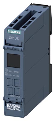
SIRIUS 3UG5 line monitoring relay

Video: SIRIUS 3UG5 line monitoring
Application |
Line monitoring relay |
||||||
|---|---|---|---|---|---|---|---|
3UG5511 |
3UG5512 |
3UG5514 |
3UG5616 |
3UG5618 |
3UG5716 |
3UG5816 |
|
Phase sequence |
✓ |
||||||
Phase failure |
-- |
✓ |
|||||
Phase asymmetry |
-- |
✓ (fixed) |
✓ |
||||
Undervoltage |
-- |
✓ |
|||||
Overvoltage |
-- |
✓ |
|||||
Frequency |
-- |
✓ |
|||||
N conductor failure |
-- |
✓ |
|||||
Correction of the direction of rotation |
-- |
✓ |
-- |
||||
SIL 1/PL c |
-- |
✓ |
-- |
✓ |
-- |
||
IO‑Link |
-- |
✓ |
|||||
Bluetooth |
-- |
✓ |
-- |
||||
✓ Available
-- Not available
Depending on the version, the relays monitor phase sequence, phase failure with and without N-conductor monitoring, phase asymmetry, frequency, undervoltage or overvoltage.
Phase asymmetry is evaluated as the difference between the greatest and the smallest phase voltage relative to the greatest phase voltage. Undervoltage or overvoltage exists when at least one phase voltage deviates by 20% from the set rated line voltage or the directly set limit values are overshot or undershot. The rms value of the voltage is measured.
With the SIRIUS 3UG5618 line monitoring relay, a wrong direction of rotation can be corrected automatically.
The 3UG5512 and 3UG5618 devices are also available as versions with Safety certification up to SIL 1/PL c according to IEC 62061 or ISO 13849‑1.
The 3UG5511 and 3UG5512 devices have a fixed function. The 3UG5514 relays can be parameterized using a potentiometer.
Особенности
- Can be used without auxiliary voltage in any network from 160 to 690 V AC worldwide thanks to wide voltage range
- Variably adjustable to overshoot, undershoot or range monitoring
- Freely configurable delay times and RESET response
- Width 22.5 mm
- Reduced stock-keeping and logistics thanks to heavily reduced device variance
- Permanent display of actual value and power system fault type in case of digital versions
- Automatic correction of the direction of rotation by distinguishing between power system faults and wrong phase sequence
- Devices with frequency monitoring
- Devices with safety certification according to SIL 1/PL c
- Devices with Bluetooth
- Communication via IO‑Link with SIRIUS 3UG5816 relay and display and transmission of actual value and power system fault type to controller
- All versions with removable terminals
- All versions with screw or spring-loaded terminals (push-in)
Область применения
The relays are used above all for mobile equipment, e.g. air conditioning compressors, refrigerating containers, building site compressors and cranes.
Function |
Application |
|---|---|
Phase sequence |
|
Phase failure |
|
Phase asymmetry |
|
Undervoltage |
|
Overvoltage |
|
Frequency |
|
Технические данные
More information | |
|---|---|
Technical specifications, see |
FAQs, see |
Equipment Manual, see |
|
3UG5511 monitoring relays
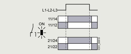
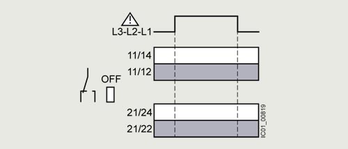
The 3UG5511 phase sequence relay monitors the phase sequence in a 3‑phase network. No adjustments are required for operation. The device has an internal power supply and works using the closed-circuit principle. If the phase sequence at the terminals L1-L2-L3 is correct, the output relay picks up after the corresponding response time and the green LED is lit. If the phase sequence is wrong, the output relay remains in its rest position.
Note:
When one phase fails, connected loads (motor windings, lamps, transformers, coils, etc.) create a feedback voltage at the terminal of the failed phase due to the network coupling. Since the 3UG5511 relays are not resistant to voltage feedback, such a phase failure is not detected. If this is required, the 3UG5512 monitoring relay must be used.
Correct phase sequence
Wrong phase sequence
3UG5512 monitoring relays
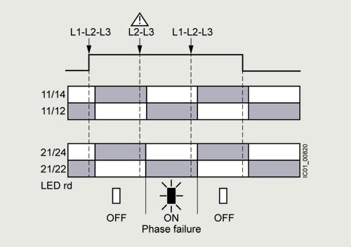
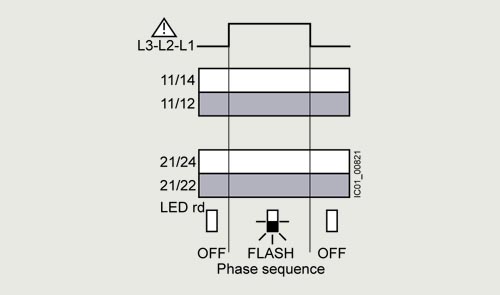
The 3UG5512 line monitoring relay monitors 3‑phase networks with regard to phase sequence, phase failure and phase asymmetry of 10%. Thanks to a special measuring method, a phase failure is reliably detected in spite of the wide voltage range from 160 to 690 V AC and feedback through the load of up to 90%. The device has an internal power supply and works using the closed-circuit principle. No adjustments are required. If the line voltage is switched on, the green LED will light up. If the phase sequence at terminals L1-L2-L3 is correct and there is no phase asymmetry, the output relay is energized. If the phase sequence is wrong or if there is phase asymmetry, the red LED flashes and the output relay remains in its rest position. If a phase fails, the red LED is permanently lit and the output relay drops. The device is also available as a version with SIL 1/PL c certification.
Note:
The red LED is a fault diagnostic indicator and does not show the current relay status. The 3UG5512 monitoring relay is suitable for line frequencies from 15 to 70 Hz.
Phase failure
Wrong phase sequence
3UG5514 monitoring relays
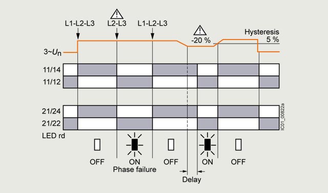
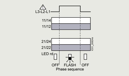
The 3UG5514 line monitoring relay monitors 3‑phase networks with regard to phase sequence, phase failure, phase asymmetry and undervoltage of 20%. The device has an internal power supply and works using the closed-circuit principle. The hysteresis is 5%. The integrated ON-delay time is adjustable from 0.1 to 20 s and responds to undervoltage. If the direction of rotation is incorrect, the device switches off immediately. Thanks to a special measuring method, a phase failure is reliably detected in spite of the wide voltage range from 160 to 690 V AC and feedback through the load of up to 80%. If the line voltage is switched on, the green LED will light up. If the phase sequence at the terminals L1-L2-L3 is correct, the output relay picks up. If the phase sequence is wrong, the red LED flashes and the output relay remains in its rest position. If a phase fails, the red LED is permanently lit and the output relay drops.
Note:
The red LED is a fault diagnostic indicator and does not show the current relay status. The 3UG5514 monitoring relay is suitable for line frequencies from 15 to 70 Hz.
Phase failure and undervoltage
Wrong phase sequence
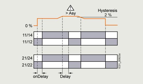
Phase asymmetry
3UG5616 and 3UG5716 monitoring relays
The 3UG5616 or 3UG5716 line monitoring relay has a wide voltage range input and an internal power supply. The device is equipped with a display and is parameterized using four buttons. The 3UG5716 relay can be additionally configured via Bluetooth using the SENTRON Powerconfig app. The 3UG5616 or 3UG5716 relay monitors 3-phase networks for phase failure, undervoltage, overvoltage, frequency and phase sequence. The hysteresis is adjustable from 0.1 to 300 V. In addition the device has two separately adjustable delay times for overshooting and undershooting limits. If the direction of rotation is incorrect, the device switches off immediately. Thanks to a special measuring method, a phase failure is reliably detected in spite of the wide voltage range from 160 to 690 V AC and feedback through the load of up to 80%.
The 3UG5616 or 3UG5716 monitoring relay can be operated on the basis of either the open-circuit or closed-circuit principle and with manual or automatic RESET.
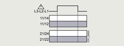
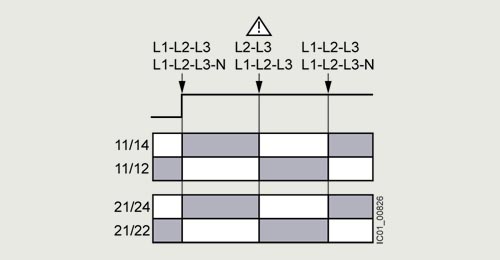
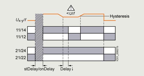
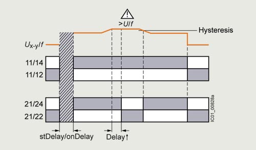
With the closed-circuit principle selected
Wrong phase sequence
Phase failure
Undervoltage, frequency undershoot
Overvoltage, frequency overshoot
3UG5816 monitoring relays
The 3UG5816 line monitoring relays have a wide voltage range input and are supplied with power through IO‑Link or from an external 24 V DC source.
The device is equipped with a display and is parameterized using four buttons. The 3UG5816 monitoring relay monitors a 3‑phase network for phase sequence, phase failure, phase asymmetry, frequency, undervoltage and overvoltage. The hysteresis is adjustable from 0.1 to 300 V.
In addition the device has two separately adjustable delay times for overshooting and undershooting limits. If the direction of rotation is incorrect or a phase fails, the device switches off immediately. Thanks to a special measuring method, a phase failure is reliably detected in spite of the wide voltage range from and potentially high feedback through the load.
The 3UG5816 monitoring relays can be operated based on either the open-circuit or closed-circuit principle and with manual or automatic RESET.
With the closed-circuit principle selected
Wrong phase sequence
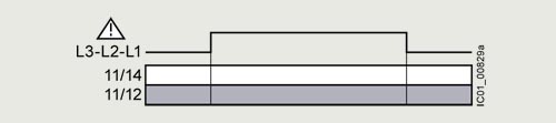
Phase failure
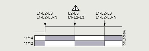
Undervoltage, frequency undershoot
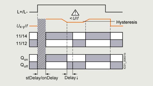
Overvoltage, frequency overshoot
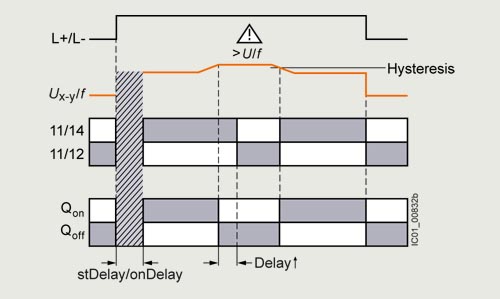
3UG5618 monitoring relays
The 3UG5618 line monitoring relay has an internal power supply and can automatically correct a wrong direction of rotation. Thanks to a special measuring method, a phase failure is reliably detected in spite of the wide voltage range from 160 to 690 V AC and feedback through the load of up to 80%.
The device is equipped with a display and is parameterized using three buttons. It monitors 3‑phase networks for phase sequence, phase failure, phase asymmetry, frequency, undervoltage and overvoltage. The hysteresis is adjustable from 0.1 to 300 V.
In addition the device has two separately adjustable delay times for overshooting and undershooting limits. The monitoring relay can be operated on the basis of either the open-circuit or closed-circuit principle and with manual or automatic RESET.
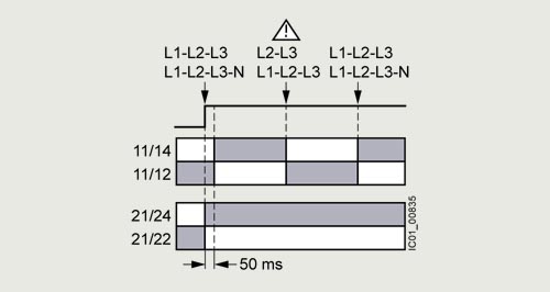
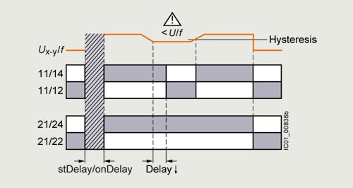
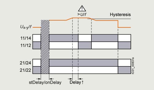
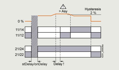
One of the CO contacts is used for warning or disconnection in the event of power system faults (voltage, frequency, asymmetry), the other one responds only to a wrong phase sequence. In conjunction with a contactor reversing assembly it is thus possible to change the direction of rotation automatically. The device is also available as a version with SIL 1/PL c certification.
With the closed-circuit principle selected
Phase failure
Undervoltage, frequency undershoot
Overvoltage, frequency overshoot
Phase asymmetry
Article number |
3UG5511-.AR20 |
3UG5512-.AR21 |
3UG5514-.BR20 |
3UG5616-.CR20 |
3UG5618-.CR21 |
3UG5716-.CR20 |
3UG5816-.AA40 |
||
|---|---|---|---|---|---|---|---|---|---|
General technical data |
|||||||||
width × height × depth |
mm |
22.5 × 100 × 90 |
|||||||
ambient temperature |
|||||||||
|
°C |
-25 ... +60 |
|||||||
|
°C |
-40 ... +85 |
|||||||
|
°C |
-40 ... +85 |
|||||||
protection class IP |
IP20 |
||||||||
mounting position |
any |
||||||||
installation altitude at height above sea level maximum |
m |
2 000 |
|||||||
electrical endurance (operating cycles) at AC-15 at 230 V typical |
100 000 |
||||||||
mechanical service life (operating cycles) typical |
10 000 000 |
||||||||
adjustable response delay time |
|||||||||
|
s |
0 ... -- |
0.1 ... 1 000 |
||||||
|
s |
0 ... -- |
0.1 ... 20 |
0.1 ... 1 000 |
|||||
performance level (PL) according to ISO 13849-1 |
-- |
PL c |
-- |
PL c |
-- |
||||
Safety Integrity Level (SIL) according to IEC 62061 |
-- |
SIL 1 |
-- |
SIL 1 |
-- |
||||
vibration resistance according to IEC 60068-2-6 |
10 ... 55 Hz: 0.35 mm |
||||||||
shock resistance according to IEC 60068-2-27 |
sinusoidal half-wave 15 g / 11 ms |
||||||||
electromagnetic compatibility |
IEC 60947-1 / IEC 61000-6-2 / IEC 61000-6-4 |
||||||||
galvanic isolation between input and output |
Yes |
||||||||
design of the electrical isolation |
galvanic isolation |
Protective separation |
|||||||
EMC emitted interference according to IEC 60947-1 |
class A |
||||||||
IO-Link protocol is supported |
No |
Yes |
|||||||
design of the interface bluetooth |
No |
Yes |
No |
||||||
Measuring circuit |
|||||||||
number of CO contacts delayed switching |
0 |
2 |
1 |
||||||
Control circuit |
|||||||||
ampacity of the output relay |
|||||||||
|
A |
3 |
|||||||
|
|||||||||
|
A |
1 |
|||||||
|
A |
0.2 |
|||||||
|
A |
0.1 |
|||||||
thermal current of the switching element with contacts maximum |
A |
5 |
|||||||
insulation voltage for overvoltage category III according to IEC 60664 with degree of pollution 3 |
V |
690 |
|||||||
surge voltage resistance |
kV |
6 |
|||||||
neutral conductor monitoring adjustable |
No |
Yes |
|||||||
control supply voltage |
|||||||||
|
|||||||||
|
V |
200 ... 690 |
-- |
||||||
|
V |
200 ... 690 |
-- |
||||||
|
|||||||||
|
V |
-- |
120 ... 400 |
-- |
|||||
|
V |
-- |
120 ... 400 |
-- |
|||||
control supply voltage at DC |
V |
-- |
24 |
||||||
operating range factor control supply voltage rated value at AC |
|||||||||
|
0.85 ... 1.1 |
-- |
|||||||
|
0.85 ... 1.1 |
-- |
|||||||
measurable voltage at AC |
|||||||||
|
160 ... 760 |
||||||||
|
160 ... 760 |
90 ... 440 |
|||||||
supply voltage frequency |
Hz |
15 ... 70 |
-- |
||||||
adjustable open/closed-circuit current principle |
No |
Yes |
|||||||
contact reliability of auxiliary contacts |
one incorrect switching operation of 100 million switching operations (17 V, 5 mA) |
||||||||
Article number |
3UG551.-1.... |
3UG551.-2.... |
||
|---|---|---|---|---|
type of electrical connection |
screw terminal |
spring-loaded terminal (push-in) |
||
tightening torque |
N·m |
0.6 ... 0.8 |
-- |
|
type of connectable conductor cross-sections |
||||
|
1x (0.5 ... 4 mm²), 2x (0.5 ... 2.5 mm²) |
1x (0.5 ... 4 mm²) |
||
|
||||
|
-- |
0.5 ... 4 mm² |
||
|
1x (0.5 ... 4 mm²), 2x (0.5 ... 2.5 mm²) |
1x (0.5 ... 2.5 mm²) |
||
|
||||
|
1x (20 ... 12), 2x (20 ... 14) |
1x (20 ... 12) |
||
|
-- |
20 ... 12 |
||