


















Обзор
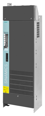
PM330 Power Module, degree of protection IP20, frame size GX
PM330 Power Modules have been specially developed for simple applications, such as driving pumps, fans and compressors with speed-controlled increasing load characteristics.
PM330 Power Modules meet the very high energy efficiency requirements particularly well, especially in this area of application, because they offer the best possible energy utilization in all operating ranges. This is achieved by the very high efficiency verified according to EN 50598, various energy-saving functions, and the automatic pulse frequency adjustment.
To reduce emissions, the PM330 Power Modules are equipped with a radio interference suppression filter as standard (in accordance with the limit values defined in Category C3). Through the use of an external line filter, the PM330 Power Modules also comply with the limits for use in the first environment (Category C2) as specified in EN 61800‑3‑1).
If required, various high-performance dv/dt filters or a Braking Module can be connected. A corresponding DC link connection is available as standard.
All available system components are coordinated exactly with the PM330 Power Modules. This enables the implementation of reliable, safe, customized control cabinet solutions. All connections can easily be accessed from the front. The internal modules are very easily accessible.
Exceptional requirements concerning motor cable lengths can be easily implemented via output reactors. Series connections are permissible here.
The PM330 Power Modules are designed for connection to grounded TN/TT systems and non-grounded IT systems. 690 V line supplies with grounded line conductor are not permitted.
The CU230P‑2 Control Unit intended for PM330 Power Modules does not have special Safety Integrated functions. Safety functions can be implemented by means of external switching devices.
1) To comply with Category C2, shielded cables must also be used between the converter and motor with a maximum permissible cable length of 150 m (492 ft). Long cables can be used if output reactors and output filters are connected (see section Load-side power components).
Интеграция
The PM330 Power Modules have the following connections and interfaces:
- PM‑IF interface to connect the PM330 Power Module to the Control Unit. The PM330 Power Module also supplies power to the Control Unit using an integrated power supply.
- Motor connection and line supply connection via screw studs
- DC-link connection for Braking Module and dv/dt filter
- PE (protective earth) connections
- Terminal block X9
- Input for external 24 V DC supply
- Input for external alarm/fault
- Input for EMERGENCY OFF / EMERGENCY STOP
- Output for 24 V DC (output current max. 250 mA)
- Control of the main contactor
- Feedback message "DC link charged"
- Terminal block X41 1)
- Dual-channel STO activation
- Feedback switch-off signal path
- Enabling STO via combination/assembly on switch S41
1) Available for Power Modules as from function release FS 04
PM330 Power Modules communicate with the Control Unit via the PM-IF interface.
For the STO and SS1 safety functions, we recommend the use of SIRIUS 3SK1 safety relays with relay outputs and 24 V supply voltage. The safety relays can be directly supplied with voltage by the Power Module. This enables the very simple implementation of the STO safety function.
- STO: 3SK1111-2AB30
- SS1: 3SK1121-2CB42
For more information see Hardware Installation Manual SINAMICS G120P PM330 Power Modules.
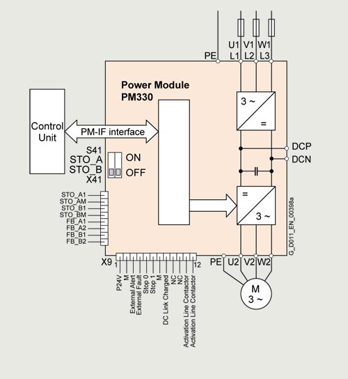
Connection example: PM330 Power Module
Power components that are available depending on the Power Module used
The following line-side power components, DC link components and load-side power components can be ordered additionally in the appropriate frames size for the Power Modules:
PM330 Power Module |
Frame sizes GX to JX |
|---|---|
Line-side power components | |
Line filters |
✓ |
Line reactor |
✓ |
DC link components | |
Braking Module with braking resistor |
✓ 1) |
Load-side power components | |
Output reactor |
✓ |
dv/dt filter plus VPL |
✓ |
dv/dt filter compact plus VPL |
✓ |
1) Available for PM330 Power Modules with line voltage from 380 V to 480 V
Технические данные
General technical specifications
PM330 Power Modules |
|
|---|---|
Input data | |
Line voltages and power ranges |
380 ... 480 V 3 AC ±10 %, 160 ... 560 kW 500 ... 690 V 3 AC ±10 %, 315 ... 630 kW |
Starting current |
< rated input current (refer to power-dependent data) |
Input frequency |
47 ... 63 Hz |
Grid requirement |
>33 line reactor required |
Output data | |
Output voltage |
0 V 3 AC … ≤ (line voltage × 0.97) |
Output current |
(refer to power-dependent data) |
Output frequency |
0 ... 150 Hz |
Pulse frequency |
Self-adjusting up to 4 kHz |
Power factor λ |
0.75 ... 0.93 |
Offset factor cos φ |
0.96 |
Further technical specifications | |
|
Overvoltage category to IEC 61800‑5‑1 |
|
Braking methods |
|
Type of cooling |
Forced air cooling AF to EN 60146 |
Protection functions |
|
Standards | |
Compliance with standards |
cULus, CE, RCM, EAC, KC, SEMI F471) |
CE marking |
According to EMC Directive 2014/30/EU, Low Voltage Directive 2014/35/EU |
RI suppression |
According to EMC product standard for variable-speed drives EN 61800‑3, "second environment". |
1) SEMI F47 for frame sizes HX (500 V to 690 V) and JX available soon
PM330 Power Modules
Line voltage 380 ... 480 V 3 AC |
PM330 Power Modules |
||||||
|---|---|---|---|---|---|---|---|
6SL3310-1PE33-0AA0 |
6SL3310-1PE33-7AA0 |
6SL3310-1PE34-6AA0 |
6SL3310-1PE35-8AA0 |
6SL3310-1PE36-6AA0 |
6SL3310-1PE37-4AA0 |
||
Rated power 1) |
|||||||
|
|||||||
|
kW |
160 |
200 |
250 |
315 |
355 |
400 |
|
hp |
200 |
250 |
300 |
400 |
450 |
500 |
|
|||||||
|
kW |
132 |
160 |
200 |
250 |
250 |
315 |
|
hp |
150 |
200 |
200 |
300 |
300 |
350 |
|
Output current at 50 Hz 3 AC |
|||||||
|
A |
300 |
370 |
460 |
585 |
655 |
735 |
|
A |
245 |
308 |
369 |
487 |
526 |
602 |
|
A |
290 |
360 |
450 |
570 |
640 |
720 |
|
A |
240 |
302 |
361 |
477 |
515 |
590 |
|
A |
240 |
296 |
368 |
468 |
491 |
551 |
|
A |
196 |
247 |
295 |
390 |
394 |
452 |
|
A |
392 |
486 |
608 |
770 |
864 |
972 |
Rated pulse frequency |
kHz |
2 |
2 |
2 |
2 |
2 |
2 |
Input current 4) |
|||||||
|
A |
317 |
375 |
469 |
597 |
668 |
750 |
|
A |
262 |
314 |
376 |
497 |
536 |
614 |
|
A |
307 |
365 |
459 |
585 |
654 |
735 |
|
A |
257 |
308 |
368 |
486 |
525 |
602 |
|
A |
254 |
300 |
375 |
477 |
501 |
562 |
|
A |
210 |
251 |
301 |
397 |
402 |
461 |
|
A |
415 |
493 |
620 |
785 |
881 |
992 |
|
Short-Circuit Current Rating ICC according to IEC in conjunction with the specified fuses |
kA |
100 |
100 |
100 |
100 |
100 |
100 |
|
Rated short-circuit current SCCR (Short-Circuit Current Rating) in accordance with UL 508C (up to 600 V) in conjunction with the specified fuses |
kA |
100 |
100 |
100 |
100 |
100 |
100 |
Minimum short-circuit current 5) |
|||||||
|
A |
3500 |
4500 |
7000 |
10000 |
11000 |
13000 |
|
A |
9500 |
14000 |
20000 |
20000 |
30000 |
30000 |
|
Efficiency η At rated current Irated (400 V/45 °C) |
% |
98 |
98 |
98.1 |
98.1 |
98 |
98.1 |
|
Power loss At rated current Irated (400 V/45 °C) |
kW |
3.642 |
4.414 |
5.125 |
6.791 |
7.687 |
8.385 |
Coolant requirements |
m3/s (ft3/s) |
0.21 (7.42) |
0.21 (7.42) |
0.21 (7.42) |
0.36 (12.7) |
0.36 (12.7) |
0.36 (12.7) |
Coolant |
Air |
Air |
Air |
Air |
Air |
Air |
|
Sound pressure level LpA (1 m) |
dB |
74 |
74 |
74 |
74 |
74 |
74 |
Power requirement 24 V DC supply |
A |
0.5 |
0.5 |
0.5 |
0.5 |
0.5 |
0.5 |
|
Line supply connection U1/L1, V1/L2, W1/L3 |
M12 screw |
M12 screw |
M12 screw |
M12 screw |
M12 screw |
M12 screw |
|
|
mm2 |
2 × 240 |
2 × 240 |
2 × 240 |
4 × 240 |
4 × 240 |
4 × 240 |
|
Motor connection U2, V2, W2 |
M12 screw |
M12 screw |
M12 screw |
M12 screw |
M12 screw |
M12 screw |
|
|
mm2 |
2 × 240 |
2 × 240 |
2 × 240 |
4 × 240 |
4 × 240 |
4 × 240 |
|
DC link connection DCP, DCN |
M12 screw |
M12 screw |
M12 screw |
M12 screw |
M12 screw |
M12 screw |
|
|
mm2 |
2 × 240 |
2 × 240 |
2 × 240 |
4 × 240 |
4 × 240 |
4 × 240 |
PE/GND connection |
M12 screw |
M12 screw |
M12 screw |
M12 screw |
M12 screw |
M12 screw |
|
|
mm2 |
3 × 240 |
3 × 240 |
3 × 240 |
(4+6) × 240 |
(4+6) × 240 |
(4+6) × 240 |
|
Cable length, max. between Power Module and motor |
|||||||
|
m (ft) |
150 (492) |
150 (492) |
150 (492) |
150 (492) |
150 (492) |
150 (492) |
|
m (ft) |
200 (656) |
200 (656) |
200 (656) |
200 (656) |
200 (656) |
200 (656) |
|
m (ft) |
300/450 (984/1476) |
300/450 (984/1476) |
300/450 (984/1476) |
300/450 (984/1476) |
300/450 (984/1476) |
300/450 (984/1476) |
Degree of protection |
IP20 |
IP20 |
IP20 |
IP20 |
IP20 |
IP20 |
|
Dimensions |
|||||||
|
mm (in) |
452 (17.8) |
452 (17.8) |
452 (17.8) |
548 (21.6) |
548 (21.6) |
548 (21.6) |
|
mm (in) |
1447 (57.0) |
1447 (57.0) |
1447 (57.0) |
1696 (66.8) |
1696 (66.8) |
1696 (66.8) |
|
mm (in) |
327.5 (12.9) |
327.5 (12.9) |
327.5 (12.9) |
393 (15.5) |
393 (15.5) |
393 (15.5) |
Frame size |
GX |
GX |
GX |
HX |
HX |
HX |
|
Weight, approx. |
kg (lb) |
98 (216) |
104 (229) |
109 (240) |
151 (333) |
157 (346) |
159 (351) |
Minimum size of control cabinet for installation of a Power Module |
|||||||
|
mm (in) |
No specifications |
No specifications |
No specifications |
800 (31.5) |
800 (31.5) |
800 (31.5) |
|
mm (in) |
No specifications |
No specifications |
No specifications |
2000 (78.7) |
2000 (78.7) |
2000 (78.7) |
|
mm (in) |
No specifications |
No specifications |
No specifications |
600 (23.6) |
600 (23.6) |
600 (23.6) |
1) Rated power of a typical 4-pole standard induction motor based on the base-load current IL or IH at 400 V 3 AC/50 Hz (kW) or 460 V 3 AC/60 Hz (hp).
2) The base-load current IL is based on the duty cycle for low overload (LO).
3) The base-load current IH is based on the duty cycle for high overload (HO).
4) The input current depends on the motor load and line impedance and applies for a line impedance corresponding to uK = 1 %. The rated input currents apply for a load at rated power (based on Irated) – these current values are specified on the rating plate.
5) 10 ms value from current-time characteristic for reliable tripping of installed protection devices. If the minimum short-circuit current is not reached, the tripping time of the fuses is increased, which can lead to damage.
Line voltage 380 ... 480 V 3 AC |
PM330 Power Modules |
|||
|---|---|---|---|---|
6SL3310-1PE38-4AA0 |
6SL3310-1PE38-8AA0 |
6SL3310-1PE41-0AA0 |
||
Rated power 1) |
||||
|
||||
|
kW |
450 |
500 |
560 |
|
hp |
500 |
600 |
700 |
|
||||
|
kW |
355 |
400 |
450 |
|
hp |
450 |
500 |
500 |
|
Output current at 50 Hz 3 AC |
||||
|
A |
840 |
910 |
1021 |
|
A |
677 |
739 |
847 |
|
A |
820 |
890 |
1000 |
|
A |
663 |
724 |
830 |
|
A |
672 |
728 |
786 |
|
A |
542 |
591 |
652 |
|
A |
1107 |
1202 |
1350 |
Rated pulse frequency |
kHz |
2 |
2 |
2 |
Input current 4) |
||||
|
A |
870 |
945 |
1061 |
|
A |
702 |
767 |
880 |
|
A |
850 |
924 |
1038 |
|
A |
687 |
751 |
862 |
|
A |
696 |
756 |
816 |
|
A |
561 |
614 |
677 |
|
A |
1147 |
1248 |
1402 |
|
Short-Circuit Current Rating ICC according to IEC in conjunction with the specified fuses |
kA |
100 |
100 |
100 |
|
Rated short-circuit current SCCR (Short-Circuit Current Rating) in accordance with UL 61800‑5‑1 (up to 600 V) in conjunction with the specified fuses |
kA |
100 |
100 |
100 |
Minimum short-circuit current 5) |
||||
|
A |
10400 |
14000 |
16000 |
|
A |
40000 |
40000 |
52000 |
|
A |
8600 |
17000 |
18000 |
|
Efficiency η At rated current Irated (400 V/45 °C) |
% |
98 |
98 |
98 |
|
Power loss At rated current Irated (400 V/45 °C) |
kW |
10.418 |
10.885 |
12.495 |
Coolant requirements |
m3/s (ft3/s) |
0.45 (15.9) |
0.45 (15.9) |
0.45 (15.9) |
Coolant |
Air |
Air |
Air |
|
Sound pressure level LpA (1 m) |
dB |
74 |
74 |
74 |
Power requirement 24 V DC supply |
A |
0.5 |
0.5 |
0.5 |
|
Line supply connection U1/L1, V1/L2, W1/L3 |
M12 screw |
M12 screw |
M12 screw |
|
|
mm2 |
6 × 240 |
6 × 240 |
6 × 240 |
|
Motor connection U2, V2, W2 |
M12 screw |
M12 screw |
M12 screw |
|
|
mm2 |
4 × 240 |
8 × 240 |
8 × 240 |
|
DC link connection DCP, DCN |
M12 screw |
M12 screw |
M12 screw |
|
|
mm2 |
4 × 240 |
4 × 240 |
4 × 240 |
PE/GND connection |
M12 screw |
M12 screw |
M12 screw |
|
|
mm2 |
6 × 240 |
6 × 240 |
6 × 240 |
|
Cable length, max. between Power Module and motor |
||||
|
m (ft) |
150 (492) |
150 (492) |
150 (492) |
|
m (ft) |
200 (656) |
200 (656) |
200 (656) |
|
m (ft) |
300/450 (984/1476) |
300/450 (984/1476) |
300/450 (984/1476) |
Degree of protection |
IP20 |
IP20 |
IP20 |
|
Dimensions |
||||
|
mm (in) |
801 (31.5) |
801 (31.5) |
801 (31.5) |
|
mm (in) |
1621 (63.8) |
1621 (63.8) |
1621 (63.8) |
|
mm (in) |
393 (15.5) |
393 (15.5) |
393 (15.5) |
Frame size |
JX |
JX |
JX |
|
Weight, approx. |
kg (lb) |
235 (518) |
250 (551) |
250 (551) |
Minimum size of control cabinet for installation of a Power Module |
||||
|
mm (in) |
No specifications |
No specifications |
No specifications |
|
mm (in) |
No specifications |
No specifications |
No specifications |
|
mm (in) |
No specifications |
No specifications |
No specifications |
1) Rated power of a typical 4-pole standard induction motor based on the base-load current IL or IH at 400 V 3 AC/50 Hz (kW) or 460 V 3 AC/60 Hz (hp).
2) The base-load current IL is based on the duty cycle for low overload (LO).
3) The base-load current IH is based on the duty cycle for high overload (HO).
4) The input current depends on the motor load and line impedance and applies for a line impedance corresponding to uK = 1 %. The rated input currents apply for a load at rated power (based on Irated) – these current values are specified on the rating plate.
5) 10 ms value from current-time characteristic for reliable tripping of installed protection devices. If the minimum short-circuit current is not reached, the tripping time of the fuses is increased, which can lead to damage.
Line voltage 500 ... 690 V 3 AC |
PM330 Power Modules |
||||
|---|---|---|---|---|---|
6SL3310-1PG33-7AA0 |
6SL3310-1PG34-0AA0 |
6SL3310-1PG34-5AA0 |
6SL3310-1PG35-2AA0 |
||
Rated power 1) |
|||||
|
|||||
|
kW |
315 |
355 |
400 |
450 |
|
hp |
350 |
400 |
450 |
450 |
|
|||||
|
kW |
250 |
315 |
355 |
400 |
|
hp |
250 |
300 |
350 |
450 |
|
Output current at 50 Hz 3 AC |
|||||
|
A |
368 |
400 |
453 |
516 |
|
A |
353 |
396 |
441 |
497 |
|
A |
340 |
393 |
430 |
480 |
|
A |
361 |
392 |
443 |
505 |
|
A |
330 |
385 |
420 |
470 |
|
A |
295 |
320 |
367 |
423 |
|
A |
272 |
314 |
348 |
394 |
|
A |
487 |
529 |
598 |
682 |
Rated pulse frequency |
kHz |
2 |
2 |
2 |
2 |
Input current 4) |
|||||
|
A |
383 |
416 |
471 |
537 |
|
A |
367 |
412 |
459 |
517 |
|
A |
354 |
409 |
447 |
499 |
|
A |
375 |
408 |
461 |
526 |
|
A |
343 |
401 |
437 |
489 |
|
A |
307 |
333 |
381 |
440 |
|
A |
283 |
327 |
362 |
410 |
|
A |
507 |
550 |
623 |
710 |
|
Short-Circuit Current Rating ICC according to IEC in conjunction with the specified fuses |
kA |
100 |
100 |
100 |
100 |
|
Rated short-circuit current SCCR (Short-Circuit Current Rating) in accordance with UL 61800‑5‑1 (up to 600 V) in conjunction with the specified fuses |
kA |
100 |
100 |
100 |
100 |
Minimum short-circuit current 5) |
|||||
|
A |
3500 |
4500 |
7000 |
8500 |
|
Efficiency η At rated current Irated (690 V/45 °C) |
% |
98.2 |
98.2 |
98.2 |
98.2 |
|
Power loss At rated current Irated (690 V/45 °C) |
kW |
5.402 |
6.191 |
6.884 |
7.716 |
Coolant requirements |
m3/s (ft3/s) |
0.362 (12.8) |
0.362 (12.8) |
0.362 (12.8) |
0.362 (12.8) |
Coolant |
Air |
Air |
Air |
Air |
|
Sound pressure level LpA (1 m) |
dB |
74 |
74 |
74 |
74 |
Power requirement 24 V DC supply |
A |
0.5 |
0.5 |
0.5 |
0.5 |
|
Line supply connection U1/L1, V1/L2, W1/L3 |
M12 screw |
M12 screw |
M12 screw |
M12 screw |
|
|
mm2 |
4 × 240 |
4 × 240 |
4 × 240 |
4 × 240 |
|
Motor connection U2, V2, W2 |
M12 screw |
M12 screw |
M12 screw |
M12 screw |
|
|
mm2 |
4 × 240 |
4 × 240 |
4 × 240 |
4 × 240 |
|
DC link connection DCP, DCN |
M12 screw |
M12 screw |
M12 screw |
M12 screw |
|
|
mm2 |
4 × 240 |
4 × 240 |
4 × 240 |
4 × 240 |
PE/GND connection |
M12 screw |
M12 screw |
M12 screw |
M12 screw |
|
|
mm2 |
(4+6) × 240 |
(4+6) × 240 |
(4+6) × 240 |
(4+6) × 240 |
|
Cable length, max. between Power Module and motor |
|||||
|
m (ft) |
150 (492) |
150 (492) |
150 (492) |
150 (492) |
|
m (ft) |
200 (656) |
200 (656) |
200 (656) |
200 (656) |
|
m (ft) |
300/450 (984/1476) |
300/450 (984/1476) |
300/450 (984/1476) |
300/450 (984/1476) |
Degree of protection |
IP20 |
IP20 |
IP20 |
IP20 |
|
Dimensions |
|||||
|
mm (in) |
548 (21.6) |
548 (21.6) |
548 (21.6) |
548 (21.6) |
|
mm (in) |
1695 (66.7) |
1695 (66.7) |
1695 (66.7) |
1695 (66.7) |
|
mm (in) |
393 (15.5) |
393 (15.5) |
393 (15.5) |
393 (15.5) |
Frame size |
HX |
HX |
HX |
HX |
|
Weight, approx. |
kg (lb) |
158 (348) |
158 (348) |
162 (357) |
162 (357) |
Minimum size of control cabinet for installation of a Power Module |
|||||
|
mm (in) |
800 (31.5) |
800 (31.5) |
800 (31.5) |
800 (31.5) |
|
mm (in) |
2000 (78.7) |
2000 (78.7) |
2000 (78.7) |
2000 (78.7) |
|
mm (in) |
600 (23.6) |
600 (23.6) |
600 (23.6) |
600 (23.6) |
1) Rated power of a typical 4-pole standard induction motor based on the base-load current IL or IH at 690 V 3 AC/50 Hz (kW) or 575 V 3 AC/60 Hz (hp).
2) The base-load current IL is based on the duty cycle for low overload (LO).
3) The base-load current IH is based on the duty cycle for high overload (HO).
4) The input current depends on the motor load and line impedance and applies for a line impedance corresponding to uK = 1 %. The rated input currents apply for a load at rated power (based on Irated) – these current values are specified on the rating plate.
5) 10 ms value from current-time characteristic for reliable tripping of installed protection devices. If the minimum short-circuit current is not reached, the tripping time of the fuses is increased, which can lead to damage.
Line voltage 500 ... 690 V 3 AC |
PM330 Power Modules |
|||
|---|---|---|---|---|
6SL3310-1PG35-8AA0 |
6SL3310-1PG36-5AA0 |
6SL3310-1PG37-2AA0 |
||
Rated power 1) |
||||
|
||||
|
kW |
500 |
560 |
630 |
|
hp |
500 |
600 |
700 |
|
||||
|
kW |
450 |
500 |
560 |
|
hp |
450 |
500 |
500 |
|
Output current at 50 Hz 3 AC |
||||
|
A |
581 |
654 |
725 |
|
A |
557 |
623 |
693 |
|
A |
535 |
595 |
665 |
|
A |
569 |
640 |
710 |
|
A |
520 |
580 |
650 |
|
A |
482 |
523 |
580 |
|
A |
444 |
476 |
532 |
|
A |
768 |
864 |
959 |
Rated pulse frequency |
kHz |
2 |
2 |
2 |
Input current 4) |
||||
|
A |
596 |
679 |
753 |
|
A |
578 |
647 |
720 |
|
A |
555 |
618 |
690 |
|
A |
591 |
665 |
737 |
|
A |
540 |
602 |
675 |
|
A |
501 |
543 |
602 |
|
A |
461 |
494 |
552 |
|
A |
798 |
897 |
995 |
|
Short-Circuit Current Rating ICC according to IEC in conjunction with the specified fuses |
kA |
100 |
100 |
100 |
|
Rated short-circuit current SCCR (Short-Circuit Current Rating) in accordance with UL 61800‑5‑1 (up to 600 V) in conjunction with the specified fuses |
kA |
100 |
100 |
100 |
Minimum short-circuit current 5) |
||||
|
A |
10000 |
11000 |
13000 |
|
Efficiency η At rated current Irated (690 V/45 °C) |
% |
98.3 |
98.3 |
98.3 |
|
Power loss At rated current Irated (690 V/45 °C) |
kW |
8.134 |
8.828 |
9.937 |
Coolant requirements |
m3/s (ft3/s) |
0.45 (15.9) |
0.45 (15.9) |
0.45 (15.9) |
Coolant |
Air |
Air |
Air |
|
Sound pressure level LpA (1 m) |
dB |
74 |
74 |
74 |
Power requirement 24 V DC supply |
A |
0.5 |
0.5 |
0.5 |
|
Line supply connection U1/L1, V1/L2, W1/L3 |
M12 screw |
M12 screw |
M12 screw |
|
|
mm2 |
6 × 240 |
6 × 240 |
6 × 240 |
|
Motor connection U2, V2, W2 |
M12 screw |
M12 screw |
M12 screw |
|
|
mm2 |
4 × 240 |
4 × 240 |
4 × 240 |
|
DC link connection DCP, DCN |
M12 screw |
M12 screw |
M12 screw |
|
|
mm2 |
4 × 240 |
4 × 240 |
4 × 240 |
PE/GND connection |
M12 screw |
M12 screw |
M12 screw |
|
|
mm2 |
6 × 240 |
6 × 240 |
6 × 240 |
|
Cable length, max. between Power Module and motor |
||||
|
m (ft) |
150 (492) |
150 (492) |
150 (492) |
|
m (ft) |
200 (656) |
200 (656) |
200 (656) |
|
m (ft) |
300/450 (984/1476) |
300/450 (984/1476) |
300/450 (984/1476) |
Degree of protection |
IP20 |
IP20 |
IP20 |
|
Dimensions |
||||
|
mm (in) |
801 (31.5) |
801 (31.5) |
801 (31.5) |
|
mm (in) |
1621 (63.8) |
1621 (63.8) |
1621 (63.8) |
|
mm (in) |
393 (15.5) |
393 (15.5) |
393 (15.5) |
Frame size |
JX |
JX |
JX |
|
Weight, approx. |
kg (lb) |
236 (520) |
236 (520) |
246 (542) |
Minimum size of control cabinet for installation of a Power Module |
||||
|
mm (in) |
No specifications |
No specifications |
No specifications |
|
mm (in) |
No specifications |
No specifications |
No specifications |
|
mm (in) |
No specifications |
No specifications |
No specifications |
1) Rated power of a typical 4-pole standard induction motor based on the base-load current IL or IH at 690 V 3 AC/50 Hz (kW) or 575 V 3 AC/60 Hz (hp).
2) The base-load current IL is based on the duty cycle for low overload (LO).
3) The base-load current IH is based on the duty cycle for high overload (HO).
4) The input current depends on the motor load and line impedance and applies for a line impedance corresponding to uK = 1 %. The rated input currents apply for a load at rated power (based on Irated) – these current values are specified on the rating plate.
5) 10 ms value from current-time characteristic for reliable tripping of installed protection devices. If the minimum short-circuit current is not reached, the tripping time of the fuses is increased, which can lead to damage.
Характеристика
Derating data
The PM330 Power Modules and the associated system components are rated for an ambient temperature of 45 °C and installation altitudes of up to 1000 m above sea level. At ambient temperatures > 45 °C, the output current must be reduced. Ambient temperatures above 55 °C are not permissible.
At installation altitudes > 1000 m above sea level, it must be taken into account that the air pressure, and therefore air density, decreases as the height increases. As a consequence, the cooling efficiency and the insulation capacity of the air also decrease. Due to the reduced cooling efficiency, it is necessary, on the one hand, to reduce the ambient temperature, and on the other hand, to lower heat loss in the built-in unit by reducing the output current.
As additional measure for installation altitudes from 2000 m up to 4000 m, an isolating transformer is required in order to reduce transient overvoltages according to EN 60664‑1.
Automatic adjustment of pulse frequency
In the factory setting, the drive starts with a pulse frequency of 4 kHz and reduces the pulse frequency automatically to the associated required frequencies when loaded. When the load decreases, the pulse frequency is increased automatically up to 4 kHz. The values of the rated current apply to a pulse frequency of 2 kHz and an ambient temperature of 45 °C and are reached at any time by the automatic adaptation of the output pulse frequency.
Current derating as a function of the installation altitude and the ambient temperature
At installation altitudes above 1000 m, the permissible output current can be compensated to a certain extent using the ambient temperature.
Current derating as a function of the installation altitude and the ambient temperature for PM330 Power Modules in frame size GX
Installation altitude above sea level |
Current derating factor (as a percentage of the rated current) for an ambient temperature of |
|||||||
m (ft) |
20 °C (68 °F) |
25 °C (77 °F) |
30 °C (86 °F) |
35 °C (95 °F) |
40 °C (104 °F) |
45 °C (113 °F) |
50 °C (122 °F) |
55 °C (131 °F) |
0 ... 1000 (0 ... 3281) |
100 % |
100 % |
100 % |
100 % |
100 % |
100 % |
93 % |
85 % |
1001 ... 1500 (3284 ... 4921) |
100 % |
100 % |
100 % |
100 % |
100 % |
96 % |
89 % |
81 % |
1501 ... 2000 (4925 ... 6562) |
100 % |
100 % |
100 % |
100 % |
99 % |
92 % |
85 % |
78 % |
2001 ... 2500 (6565 ... 8202) |
100 % |
100 % |
100 % |
100 % |
94 % |
88 % |
81 % |
74 % |
2501 ... 3000 (8205 ... 9843) |
100 % |
100 % |
100 % |
96 % |
90 % |
83 % |
77 % |
71 % |
3001 ... 3500 (9846 ... 11483) |
100 % |
100 % |
97 % |
91 % |
85 % |
79 % |
73 % |
67 % |
3501 ... 4000 (11486 ... 13123) |
100 % |
98 % |
92 % |
86 % |
81 % |
75 % |
69 % |
64 % |
Current derating as a function of the installation altitude and the ambient temperature for PM330 Power Modules in frame sizes HX and JX
Installation altitude above sea level |
Current derating factor (as a percentage of the rated current) for an ambient temperature of |
|||||||
m (ft) |
20 °C (68 °F) |
25 °C (77 °F) |
30 °C (86 °F) |
35 °C (95 °F) |
40 °C (104 °F) |
45 °C (113 °F) |
50 °C (122 °F) |
55 °C (131 °F) |
0 ... 1000 (0 ... 3281) |
100 % |
100 % |
100 % |
100 % |
100 % |
100 % |
93 % |
85 % |
1001 ... 1500 (3284 ... 4921) |
100 % |
100 % |
100 % |
100 % |
100 % |
97 % |
89 % |
82 % |
1501 ... 2000 (4925 ... 6562) |
100 % |
100 % |
100 % |
100 % |
100 % |
93 % |
86 % |
79 % |
2001 ... 2500 (6565 ... 8202) |
100 % |
100 % |
100 % |
100 % |
97 % |
90 % |
83 % |
76 % |
2501 ... 3000 (8205 ... 9843) |
100 % |
100 % |
100 % |
100 % |
94 % |
87 % |
80 % |
74 % |
3001 ... 3500 (9846 ... 11483) |
100 % |
100 % |
100 % |
96 % |
90 % |
84 % |
77 % |
71 % |
3501 ... 4000 (11486 ... 13123) |
100 % |
100 % |
98 % |
92 % |
86 % |
80 % |
74 % |
68 % |
Note:
The connected motors and power elements must be considered separately.
Note:
The operating temperature ranges of the Control Units must be taken into account (see technical specifications of Control Units).
Current derating as a function of the line voltage
PM330 Power Modules supply a constant power over the full permissible range of line voltage.
The constant power results in current derating as a function of the line voltage.
PM330 Power Module |
Rated power based on the base-load current IL at 400 V |
Rated output current in A at a line voltage of |
||||
|---|---|---|---|---|---|---|
6SL3310- |
kW |
380 V |
400 V |
415 V 1) |
460 V |
480 V |
1PE33-0AA0 |
160 |
300 |
300 |
290 |
259 |
245 |
1PE33-7AA0 |
200 |
370 |
370 |
358 |
325 |
308 |
1PE34-6AA0 |
250 |
460 |
460 |
443 |
393 |
369 |
1PE35-8AA0 |
315 |
585 |
585 |
567 |
513 |
487 |
1PE36-6AA0 |
355 |
655 |
655 |
631 |
559 |
526 |
1PE37-4AA0 |
400 |
735 |
735 |
710 |
636 |
602 |
1PE38-4AA0 |
450 |
840 |
840 |
810 |
717 |
677 |
1PE38-8AA0 |
500 |
910 |
910 |
877 |
791 |
739 |
1PE41-0AA0 |
560 |
1021 |
1021 |
988 |
891 |
847 |
1) Full rated current up to 440 V, therefore no derating for 415 V ±5%.
PM330 Power Module |
Rated power based on the base-load current IL at 690 V |
Rated output current in A at a line voltage of |
||||
|---|---|---|---|---|---|---|
6SL3310- |
kW |
500 V |
575 V |
600 V |
660 V |
690 V |
1PG33-7AA0 |
315 |
368 |
357 |
353 |
344 |
340 |
1PG34-0AA0 |
355 |
400 |
397 |
396 |
394 |
393 |
1PG34-5AA0 |
400 |
453 |
444 |
441 |
434 |
430 |
1PG35-2AA0 |
450 |
516 |
502 |
497 |
486 |
480 |
1PG35-8AA0 |
500 |
581 |
563 |
554 |
542 |
535 |
1PG36-5AA0 |
560 |
654 |
631 |
623 |
604 |
595 |
1PG37-2AA0 |
630 |
725 |
701 |
693 |
674 |
665 |
Operating ranges
An additional dimensioning aid is available for all PM330 Power Modules. The purpose of this aid is to ensure the constant reliable operation of the converter, in particular with regard to service life expectancy.
The dimensioning aid clearly distinguishes between continuous operating ranges and short-time operating ranges. As a result, due consideration can be given to operating ranges when the plant is configured. For further details, please refer to the diagram below and the explanatory text.
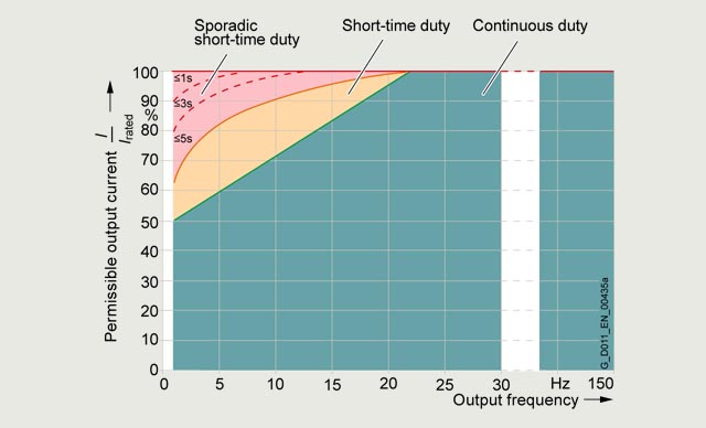
Continuous operation (green area) permissible.
Short-time operation (yellow area) permissible for 2 % of the total operating period without significant reduction in the converter service life; no overload reaction triggered by the thermal monitoring model.
Sporadic short-time operation (red area) permissible for only very short, rare operating states lasting less than 0.1 % of the total operating period without significant reduction in the converter service life; no overload reaction triggered by the thermal monitoring model on condition of compliance with the duty times specified in the diagram.
Overload capability
PM330 Power Modules have an overload reserve e.g. to handle breakaway torques. If larger surge loads occur, this must be taken into account in the configuration. In drives with overload requirements, the appropriate base-load current must, therefore, be used as a basis for the required load.
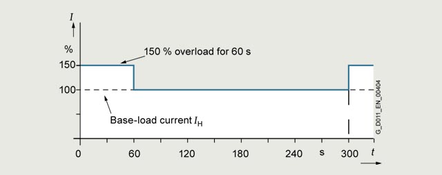
The unit can operate in two different duty cycles in the permissible continuous operating range shown in the diagram (green area). Depending on how the system is dimensioned, the relevant base-load current is effective as a rated quantity.
The criterion for overload is that the converter is operated with its base-load current before and after the overload occurs on the basis of a duty cycle duration of 300 s.
The base-load current for a low overload IL is the basis for a duty cycle of 110 % for 60 s or 135 % for 3 s.
The base-load current IH for a high overload is based on a duty cycle of 150 % for 60 s.
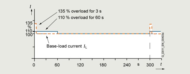
Overload capability, low overload
Overload capability, high overload
Чертеж
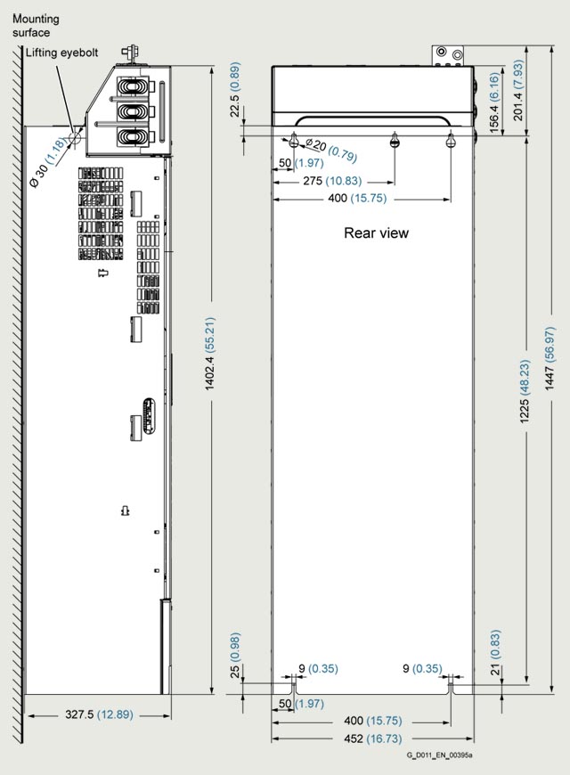
Principle dimension drawing and drill pattern for PM330 Power Modules, frame size GX
Secured with M8 bolts
Ventilation clearance required at top and bottom: 200 mm (7.87 in)
Ventilation clearance required at sides: 30 mm (1.18 in)
Ventilation clearance required at front: 30 mm (1.18 in)
The PM330 Power Modules are designed for installation in a control cabinet.
All dimensions in mm (values in brackets are in inches).
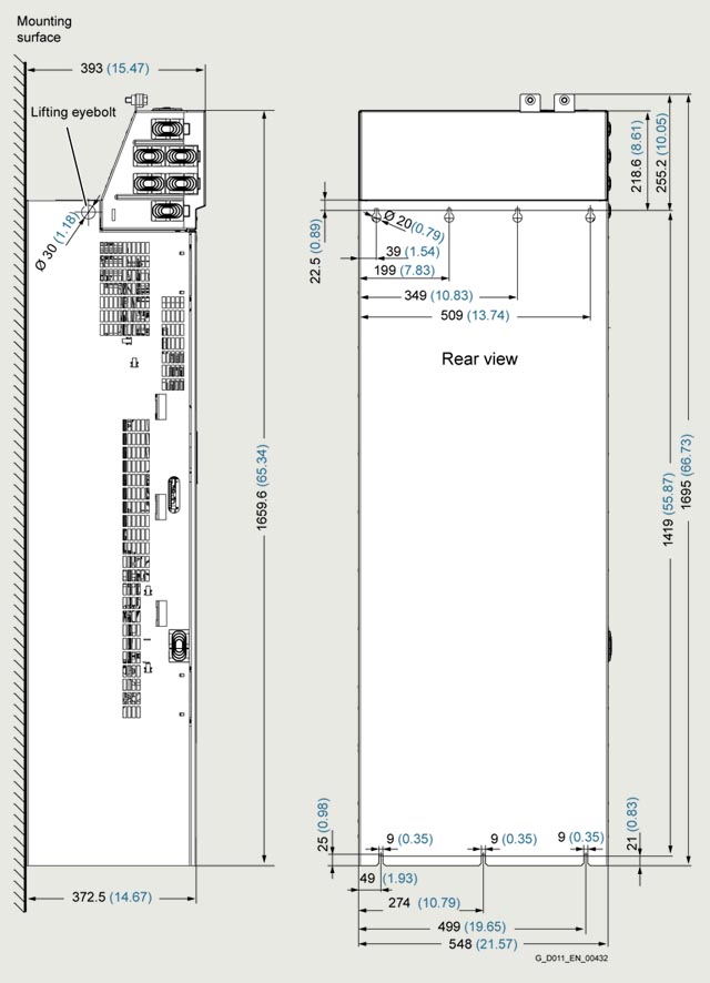
Principle dimension drawing and drill pattern for PM330 Power Modules, frame size HX
Secured with M8 bolts
Ventilation clearance required at the top: 200 mm (7.87 in)
Ventilation clearance required at the bottom: 250 mm (9.84 in)
Ventilation clearance required at sides: 30 mm (1.18 in)
Ventilation clearance required at front: 100 mm (3.94 in)
The PM330 Power Modules are designed for installation in a control cabinet.
All dimensions in mm (values in brackets are in inches).
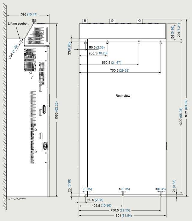
Principle dimension drawing and drill pattern for PM330 Power Modules, frame size JX (available soon)
Secured with M8 bolts
Ventilation clearance required at the top: 200 mm (7.87 in)
Ventilation clearance required at the bottom: 250 mm (9.84 in)
Ventilation clearance required at sides: 30 mm (1.18 in)
Ventilation clearance required at front: 100 mm (3.94 in)
The PM330 Power Modules are designed for installation in a control cabinet.
All dimensions in mm (values in brackets are in inches).