


















-
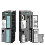 CU230P-2 Control Units
-
 PM330 Power Modules, 160 kW to 630 kW
-
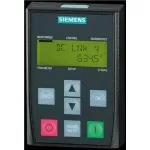 Принадлежности и запасные части для ПЧ SINAMICS G120P
Обзор
- Введение
- Преобразователи для насосов, вентиляторов, компрессоров SINAMICS G120P
- Управляющие модули CU230P-2
- Силовые модули PM230
- Рекомендованные активные компоненты со стороны сети
- Дополнительные системные компоненты
- Запасные части
Область применения
The specialist for pump, fan and compressor applications
SINAMICS G120P is ideally suited to pump applications (centrifugal pumps, oscillating and rotating pumps), fan applications (axial and radial fans) and compressor applications (cooling compressors, air and gas compressors). They are deployed in industrial environments, in the process industry and water industry and in building automation.
SINAMICS G120P is ideally suited for the following applications:
- Circulating pumps for heating and cooling systems
- Pumps for pressure boosting stations
- Level control
- Fans in cooling towers
- Fans for air intake and discharge
- Fans for tunnels and multi-storey car parks
- Fans for stairwells
- Compressors for supplying compressed air
Reliable operation in harsh environments
SINAMICS G120P is suitable for use under harsh environmental conditions:
- High degree of protection IP55 for installation outside the control cabinet
- Degree of protection IP20 for use in the control cabinet
- Operation possible at ambient temperatures of up to 60 °C (140 °F)
- Coated modules for increased resistance to humidity and dust
Функции
Technology function
Functions specific to pumps, fans and compressors are already integrated, e.g.:
-
Automatic restart
Application restart after a power failure or fault occurrence -
Flying restart
Connection of the converter when the motor is running -
Flux reduction
Automatic adaptation of the motor current to the prevailing load conditions in U/f control mode (ECO mode) as well as in sensorless vector control mode -
Cascade connection
Load-dependent connection and disconnection of a maximum of three additional motors by the converter in order to provide a largely constant output power (implemented by means of an additional external circuit) -
Hibernation mode
Startup or shutdown of the drive when the relevant value drops below an external setpoint or the internal PID controller setpoint -
Real-time clock
For time-dependent process controls, e.g. to reduce the temperature of a heating control at night and with automatic daylight saving/standard time switchover -
Freely programmable logical function blocks
For simulating simple PLC functions
Functions especially for building technology as well as heating/air conditioning/ventilation applications
-
4 integrated PID controllers
One PID controller for controlling the drive speed as a function of pressure, temperature, flowrate, fill level, air quality and other process variables, and a further three PID controllers with freely configurable outputs, e.g. for controlling valves (heating, cooling) or flaps -
Emergency mode
Special converter operating mode that enhances the availability of the drive system in the event of a fire
Multi-zone controller - Closed-loop control of a zone with up to 3 sensors for pressure or temperature, or
- Closed-loop control of two independent zones, each with one sensor
-
Bypass mode
When the setpoint is reached or a fault occurs, the system changes over to line operation (implemented by means of an additional external circuit) - Programmable time switches
Конфигурация
The following electronic configuring guides and engineering tools are available for SINAMICS G120P converters:
SinaSave energy efficiency tool
Use SinaSave to calculate potential energy savings
The web-based tool SinaSave can be used to estimate the potential savings which can be achieved over the entire lifecycle, e.g. for pump and fan applications, thanks to SINAMICS. The tool takes into consideration all important plant-specific quantities, such as the power and load data of the application, the relevant control mode and the operation profile for the application in question. The result delivered by the tool specifies the potential energy savings which can be achieved with the specific application in conjunction with the Integrated Drive System or the drive component. The tool also provides a monetary evaluation of the potential savings and estimates the payback period.
Siemens Product Configurator
The Siemens Product Configurator helps you to configure the optimum drive technology products for a number of applications – starting with gearboxes, motors, converters as well as the associated options and components and ending with controllers, software licenses and connection systems.
The Siemens Product Configurator can be used on the internet without requiring any installation. The Siemens Product Configurator can be found in SiePortal at the following address:
www.siemens.com/spc
SIZER for Siemens Drives engineering tool
Configuring made simple and systematic
The SIZER for Siemens Drives engineering tool is used to configure low-voltage drive systems: Using the application as the prime reference, this tool provides step-by-step support in defining the mechanical system and designing converters, motors and gearboxes. It also helps the user to configure other system components and to design open-loop and closed-loop control functions. In addition to engineering results such as characteristics, technical specifications and installation and dimensional drawings, SIZER for Siemens Drives also provides calculations pertaining to performance and load-dependent power requirements.
SIZER WEB ENGINEERING engineering tool
Drive engineering – flexible, customized and user-friendly
A solution for a drive task can be identified quickly with the web-based tool: menu-prompted workflows guide the user through the technical selection and dimensioning of products and drive systems, including the accessories.
Based on an integrated inquiry functionality, SIZER WEB ENGINEERING also offers you special customized solutions for applications which cannot be addressed using "standard products"; i.e. the focus is on flexibility and customized solutions.
Comprehensive documentation, such as data sheets, startup calculations, dimensional drawings, offer documentation and a lot more are integrated in the tool. The result: Customized solutions for any drive task.
The product groups supported are:
- High-voltage motors
- Low-voltage motors
- Medium-voltage converters
- Low-voltage converters
- DC converters
The tool can also be used to design the following drive systems:
- Medium-voltage systems
- Low-voltage systems
- Basic single-axis applications for pumps, fans, and compressors
- Complex applications (on condition that: SIZER for Siemens Drives is installed)
STARTER commissioning tool
Commissioning and diagnostics – intelligent and easy
The STARTER commissioning tool allows menu-prompted commissioning, optimization and diagnostics. Apart from the SINAMICS drives, STARTER is also suitable for MICROMASTER 4 devices.
SINAMICS Startdrive commissioning tool
SINAMICS engineering in the TIA Portal
SINAMICS Startdrive is a tool for configuring, commissioning, and diagnosing the SINAMICS family of drives and is integrated into the TIA Portal. SINAMICS Startdrive can be used to implement drive tasks with the SINAMICS G120, SINAMICS G120C, SINAMICS G110M, SINAMICS G120D and SINAMICS G120P converter series. The commissioning tool has been optimized with regard to user-friendliness and consistent use of the TIA Portal benefits of a common working environment for PLC, HMI and drives.
Drive ES engineering system
Drive ES is the engineering system that can be used to integrate the communication, configuration and data management functions of Siemens drive technology into the SIMATIC automation world easily, efficiently and cost-effectively. Two software packages are available for SINAMICS – Drive ES Basic and Drive ES PCS 7.
You can find more information about the Drive ES engineering system in the chapter Engineering Tools.
More information about the Drive ES engineering system is available on the internet at
www.siemens.com/drive-es
Технические данные
Unless explicitly specified otherwise, the following technical specifications are valid for all the following components of the SINAMICS G120P pump, fan, compressor converters.
SINAMICS G120P | |
|---|---|
Mechanical specifications | |
Vibratory load |
|
|
|
|
Class 1M2 Deflection: 1.5 mm at 5 ... 9 Hz |
|
Class 1M2 Deflection: 1.5 mm at 5 ... 9 Hz |
|
|
|
Class 2M2 |
|
Class 2M3 |
|
Test FC according to EN 60068‑2‑6 Deflection: ±1.5 mm at 5 ... 9 Hz |
|
|
|
Class 3M1 |
|
Test FC according to EN 60068‑2‑6 Deflection: 0.075 mm at 10 ... 58 Hz |
Shock load |
|
|
|
|
Class 1M2 |
|
Test FC according to EN 60068‑2‑6 Deflection: ±1.5 mm at 5 ... 9 Hz |
|
|
|
Class 2M2 |
|
Class 2M3 |
|
Test FC according to EN 60068‑2‑6 Deflection: ±1.5 mm at 5 ... 9 Hz |
|
|
|
Class 3M2 |
|
Class 3M1 |
|
Test Ea according to EN 60068‑2‑27 Acceleration: 49 m/s2 (5 × g) at 30 ms |
Ambient conditions | |
|
Protection class According to EN 61800‑5‑1 |
Class I (with protective conductor system) and class III (PELV) |
Touch protection |
According to EN 50274 and DGUV Regulation 3 when used for the intended purpose |
Permissible ambient and coolant temperature (air) during operation for line-side power components and Power Modules |
|
|
Frame sizes FSA to FSC: -10 ... +40 °C (14 ... 104 °F) without derating Frame size GX to JX: 0 ... 45 °C (32 ... 113 °F) without derating |
|
Frame sizes FSA to FSC: -10 ... +50 °C (14 ... 122 °F) without derating Frame size GX to JX: 0 ... 45 °C (32 ... 113 °F) without derating |
Installation altitude |
Up to 1000 m (3281 ft) above sea level without derating, |
Permissible ambient and coolant temperature (air) during operation for Control Units and supplementary system components |
With CU230P‑2 HVAC/DP with/without blanking cover: -10 ... +60 °C (14 ... 140 °F) With CU230P‑2 PN with/without blanking cover: -10 ... +55 °C (14 ... 131 °F) With IOP‑2/BOP‑2: 0 ... 50 °C (32 ... 122 °F) Derating of 3 K/1000 m applies to Control Units as of an installation altitude of 1000 m (3281 ft) above sea level. |
Climatic ambient conditions |
|
|
|
|
Temperature -40 ... +70 °C (-40 ... +158 °F) |
|
Class 1K3 |
|
Class 1K4 |
|
|
|
Class 2K4 |
|
Class 2K3 |
|
|
|
Class 3K3 |
|
Class 3K3 |
Environmental class/harmful chemical substances |
|
|
Class 1C2 |
|
Class 2C2 |
|
Class 3C2 |
Organic/biological influences |
|
|
Class 1B1 |
|
Class 2B1 |
|
Class 3B1 |
|
Degree of pollution According to EN 61800‑5‑1 |
2 |
Standards | |
Compliance with standards |
|
|
UL, cUL 3), CE, RCM, SEMI F47 |
|
cULus, CE, RCM, EAC, KC, SEMI F47 4) |
CE marking |
According to Low Voltage Directive 2014/35/EU, EMC Directive 2014/30/EU |
|
EMC Directive According to EN 61800-3 |
|
|
The Power Modules comply with Category C2 according to EN 61800‑3. |
|
The Power Modules comply with the limit values for low-frequency line harmonics and conducted interference according to Category C1. They comply with the limit values for field-conducted interference emissions according to Category C2. |
|
The Power Modules comply with Category C2 according to EN 61800‑3. |
|
The Power Modules comply with Category C3 according to EN 61800‑3. |
|
Category C3 5) |
|
Category C2 6) |
Deviations from the specified classes are underlined.
1) In transport packaging.
2) In product packaging.
3) Applies to PM230 Power Modules frame sizes FSA to FSC and PM240P‑2 Power Modules with integrated line filter class A.
4) SEMI F47 for PM330 Power Modules, frame sizes HX (500 V to 690 V) and JX, available soon.
5) Standard configuration: Devices installed in the control cabinet with EMC-compatible configuration, line reactor uK = 2 %, shielded motor cable (e.g. Protoflex EMC) with max. 150 m cable length. Line harmonics acc. to EN 61000‑2‑4: Class 3, THD(U) total = 10 % for typical line conditions (RSC > 10);THD(I) total: typically 30 ... 45 % (15 > RSC > 50).
6) Use in the second environment, for boundary conditions refer to 6).
7)For boundary conditions see 6), cabinet is configured accordingly in version A.
Note:
The EMC product standard EN 61800-3 does not apply directly to a frequency converter but to a PDS (Power Drive System), which comprises the complete circuitry, motor and cables in addition to the converter. The frequency converters on their own do not generally require identification according to the EMC Directive.
Compliance with standards
CE marking

The SINAMICS G120P converters meet the requirements of the Low-Voltage Directive 2014/35/EC.
Low-Voltage Directive
The converters comply with the following standards listed in the official journal of the EU:
- EN 60204
Safety of machinery, electrical equipment of machines - EN 61800‑5‑1
Electrical power drive systems with variable speed – Part 5‑1: Requirements regarding safety – electrical, thermal, and energy requirements
UL listing

Converters in UL category NMMS certified to UL and cUL, in compliance with UL508C or UL61800‑5‑1. UL File Number E121068 and E192450.
For use in environments with pollution degree 2.
See also on the internet at http://www.ul.com
Machinery directive
The converters are suitable for installation in machines. Compliance with the Machinery Directive 2006/42/EC requires a separate certificate of conformity. This must be provided by the plant construction company or the organization marketing the machine.
Functional safety
SINAMICS G120P are not intended for use in installations with functional safety as defined by ISO 13849‑1, IEC 61508‑x.
EMC Directive
- EN 61800‑3
Variable-speed electric drives
Part 3: EMC product standard including specific test methods
The following explanatory information applies to SINAMICS G120P converters supplied by Siemens AG:
- The EMC product standard EN 61800-3 does not apply directly to a converter but to a PDS (Power Drive System), which comprises the complete circuitry, motor and cables in addition to the converter.
- Converters are normally only supplied to experts for installation in machines or systems. A converter must, therefore, only be considered as a component which, on its own, is not subject to the EMC product standard EN 61800-3. The converter's operating instructions, however, specifies the conditions regarding compliance with the product standard if the converter is expanded to become a PDS. For a PDS, the EMC Directive in the EU is complied with by observing the product standard EN 61800-3 for variable-speed electric drive systems. The converters on their own do not generally require identification according to the EMC Directive.
- Different categories C1 to C4 have been defined in accordance with the environment of the PDS at the operating location:
- Category C1: Drive systems for rated voltages < 1000 V for use in the first environment
- Category C2: Stationary drive systems not connected by means of a plug connector for rated voltages < 1000 V. When used in the first environment, the system must be installed and commissioned by personnel familiar with EMC requirements. A warning note is required.
- Category C3: Drive systems for rated voltages < 1000 V for exclusive use in the second environment. A warning note is required.
- Category C4: Drive systems for rated voltages ≥ 1000 V or for rated currents ≥ 400 A or for use in complex systems in the second environment. An EMC plan must be created.
- The EMC product standard EN 61800‑3 also defines limit values for conducted interference and radiated interference for the "second environment" (= industrial power supply systems that do not supply households). These limit values are below the limit values of filter class A to EN 55011. Unfiltered converters can be used in industrial environments as long as they are part of a system that contains line filters on the higher-level infeed side.
- With SINAMICS G120P, Power Drive Systems (PDS) that fulfill the EMC product standard EN 61800-3 can be configured when observing the installation instructions in the product documentation.
- A differentiation must be made between the product standards for electrical drive systems (PDS) of the range of standards EN 61800 (of which Part 3 covers EMC topics) and the product standards for the devices/systems/machines, etc. This will probably not result in any changes in the practical use of converters. Since converters are always part of a PDS and these are part of a machine, the machine manufacturer must observe various standards depending on their type and environment (e.g. EN 61000‑3‑2 for line harmonics and EN 55011 for radio interference). The product standard for PDS on its own is, therefore, either insufficient or irrelevant.
- With respect to the compliance with limits for line supply harmonics, the EMC product standard EN 61800‑3 for PDS refers to compliance with the EN 61000‑3‑2 and EN 61000‑3‑12 standards. EN 61000‑2‑4 applies for devices >75 A.
- Regardless of the configuration with SINAMICS G120P and its components, the machine construction company (OEM) can also apply other measures to ensure that the machine complies with the EU EMC Directive. The EU EMC Directive is generally fulfilled when the relevant EMC product standards are observed. If they are not available, the generic standards (e.g. EN 61000‑x‑x) can be used instead. It is important that the conducted and emitted interference at the line supply connection point and outside the machine remain below the relevant limit values. Any suitable technical measures can be applied to ensure this.
SEMI F47
SEMI F47 is an industry standard relating to the immunity to voltage dips. This includes the requirement that industrial equipment must be able to tolerate defined dips or drops of the line supply voltage. As a result, industrial equipment that fulfills this standard is more reliable and productive.
All Power Modules of the SINAMICS G120P product family fulfill the latest standard SEMI F47-0706 1). In the case of a voltage dip, defined in accordance with SEMI F47‑0706, these drives either continue to supply a defined output current, or using an automatic restart function, continue to operate as expected.
1) SEMI F47 for PM330 Power Modules, frame sizes HX (500 V to 690 V) and JX, available soon
EAC approval for Russia/Belarus/Kazakhstan/Armenia

Since 2013-02-15, Russia, Kazakhstan, Belarus and Armenia have been united in the Eurasian EAC customs union. An EAC approval as replacement for the GOST mark is required for all products that are to be sold in Russia.
All devices delivered to the customs union must have these customs certifications.
RCM approval for Australia
The RCM mark is required for marketing Siemens electronic devices in Australia. Electronic devices must provide proof of EMC clearance in Australia, similar to the CE marking of conformity laid down by the EMC directive applicable in the EU. The converters must be marked accordingly. These requirements have been in force since October 1, 1999.
On March 1, 2016, the C-Tick mark was replaced by the RCM mark.
KC approval for South Korea
KC approval (formerly KCC) is required for the distribution of our electrical equipment in South Korea. Electronic devices that are covered by the EU Directive on Electromagnetic Compatibility must provide an EMC certificate issued by a resident authority in South Korea. The converters must be marked accordingly. This requirement has been in force since January 24, 2011.
Power Modules
General technical specifications
Power Modules |
PM230 |
PM240P-2 |
PM330 |
|---|---|---|---|
System operating voltage |
380 ... 480 V 3 AC ±10 % |
380 ... 480 V 3 AC ±10 % 500 ... 690 V 3 AC ±10 % |
380 ... 480 V 3 AC ±10 % 500 ... 690 V 3 AC ±10 % |
Grid requirement |
>100 |
>25 |
>33 line reactor recommended |
Input frequency |
47 ... 63 Hz |
47 ... 63 Hz |
47 ... 63 Hz |
Output frequency |
|||
|
0 ... 550 Hz |
0 ... 550 Hz |
0 ... 150 Hz |
|
0 ... 240 Hz |
0 ... 200 Hz |
0 ... 150 Hz |
Pulse frequency |
4 kHz Higher pulse frequencies up to 16 kHz, see derating data |
At 380 ... 480 V 3 AC: Higher pulse frequencies up to 16 kHz, see derating data At 500 ... 690 V 3 AC: |
Self-adjusting up to 4 kHz |
Power factor λ |
0.9 |
0.9 ... 0.95 |
0.75 ... 0.93 |
Offset factor cos φ |
0.95 |
0.99 |
0.96 |
Efficiency |
≤97 % |
>97 % |
>98 % |
|
Output voltage, max. In % of input voltage |
95 % |
95 % |
97 % |
Overload capability |
|||
Note: When the overload capability is used, the base-load current IL is not reduced. |
FSA to FSC: FSD to FSF: |
1.35 × base-load current IL (i.e. 135 % overload) for 3 s plus 1.1 × base-load current IL (i.e. 110 % overload) for 57 s within a cycle time of 300 s |
1.35 × base-load current IL (i.e. 135 % overload) for 3 s or 1.1 × base-load current IL (i.e. 110 % overload) for 60 s within a cycle time of 300 s |
Note: When the overload capability is used, the base-load current IH is not reduced. |
FSA to FSC: FSD to FSF: |
1.5 × base-load current IH (i. e. 150 % overload) for 60 s within a cycle time of 300 s |
1.5 × base-load current IH (i. e. 150 % overload) for 60 s within a cycle time of 300 s |
Possible braking methods |
DC braking |
DC braking Compound braking |
DC braking Dynamic braking with optional Braking Module |
Overvoltage category acc. to IEC 61800‑5‑1 |
III |
III |
Supply circuits: III |
Degree of protection |
IP55/UL Type 12 (with IOP‑2, BOP‑2 or blanking cover) IP20 (standard) |
IP20 |
IP20 |
Cooling |
Power units with increased air cooling using integrated fans |
Internal air cooling, power units with increased air cooling by built-in fans |
Internal air cooling, power units with increased air cooling by built-in fans |
Protection functions |
|
||
|
Short-Circuit Current Rating SCCR acc. to UL (Short-Circuit Current Rating) 2) |
Degree of protection IP55 frame sizes FSA to FSC: 40 kA Degree of protection IP55 frame sizes FSD to FSF and degree of protection IP20: 65 kA |
100 kA |
100 kA 3) |
|
Short-Circuit Current Rating ICC acc. to IEC 3) |
– |
100 kA |
100 kA 3) |
1) Does not apply in conjunction with option L01.
2) Applies to industrial control panel installations according to NEC Article 409 or UL 508A/508C or UL 61800-5-1.
3) In combination with the fuses specified in section Recommended line-side overcurrent protection devices and/or Load-side power components.
Дополнительно
Optional accessories
Shield connection kit 1 for CU230P‑2 HVAC/DP Control Units
Shield connection kit 1 offers optimum shield connection and strain relief for all signal and communication cables. It includes a matching shield connection plate and all of the necessary connecting and retaining elements for mounting.
Shield connection kit 3 for CU230P‑2 PN, CU240E‑2 PN and CU240E‑2 PN‑F Control Units
Shield connection kit 3 offers optimum shield connection and strain relief for all signal and communication cables. It includes a matching shield connection plate and all of the necessary connecting and retaining elements for mounting.
SINAMICS memory card (SD card)
The parameter settings for a converter can be stored on the SINAMICS SD memory card. The SINAMICS SD card can be used to pre-parameterize converters and to clone complete converter data sets. When service is required, e.g. after the converter has been replaced and the data have been downloaded from the memory card the drive system is immediately ready for use again. The associated slot is located on the top of the Control Unit.
PC converter connection kit 2
For controlling and commissioning the converter directly from a PC, if the STARTER commissioning tool has been installed on the PC.
Installation kit for line-side cable connection, left, for PM330 Power Modules
This installation kit allows supply cables to be brought in from the left-hand side of frame size GX and HX PM330 Power Modules. It is then possible to install the Power Module in the cabinet without any clearance at the top.
Spare parts
Mounting set for PM230 and PM240P-2 Power Modules
Depending on the frame size, different mounting sets are available for PM230 and PM240P-2 Power Modules.
Fan units for PM230 Power Modules
The PM230 Power Module is equipped with an internal and an external fan unit. Both of these can be replaced if necessary.
Replacement fans
The fans for PM240P-2 and PM330 Power Modules are available to order as replacement fans.
Дальнейшая информация
You may also be interested in these frequency converters:
- More performance in the control cabinet in IP20 degree of protection ⇒ SINAMICS G130, SINAMICS G150
- With positioning function for distributed drive solutions in IP65 degree of protection ⇒ SINAMICS G120D
- With positioning function in the control cabinet in IP20 degree of protection ⇒ SINAMICS S110, SINAMICS S120, SINAMICS S150