


















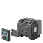
Обзор
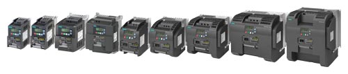
SINAMICS V20 converters, frame sizes: FSAA, FSAB, FSAC, FSAD, FSA, FSB, FSC, FSD, and FSE
SINAMICS V20 – The cost-effective, reliable and easy-to-use converter for basic applications
Today, in an increasing number of applications in plant and machinery construction, individual automation and drive solutions are demanded that automate simple motion sequences with low associated requirements.
The compact SINAMICS V20, the basic performance converter, offers a simple and cost-effective drive solution for these types of applications. SINAMICS V20 sets itself apart with its quick commissioning times, ease of operation, robustness and cost-efficiency.
With nine frame sizes, it covers a power range extending from 0.12 kW to 30 kW (0.16 hp to 40 hp).
Minimizing costs
SINAMICS V20 keeps engineering and commissioning costs as well as those in operation as low as possible. To increase energy efficiency, the converter is equipped with a control technique to achieve optimum energy efficiency through automatic flux reduction. Not only this, it displays the actual energy consumption and has additional, integrated energy-saving functions. This allows energy consumption to be slashed drastically.
Особенности
Easy to install
- Push-through and wall mounting
- Side-by-side mounting possible for both
- Compact installation allows smaller cabinets to be used
- Push-through mounting for frame sizes FSB, FSC, FSD, and FSE allows for simpler cabinet cooling
- Frame sizes FSAA, FSAB, FSAC, and FSAD (230 V 1 AC) are significantly smaller compared to the previous frame sizes FSA, FSB, and FSC within the same power range
- Plug & Play
- Can be run "out-of-the-box" without other options
- Basic operator actions at a built-in BOP (Basic Operator Panel)
- Connection of SINAMICS V20 with USS or Modbus RTU via terminals
- Easy integration into existing systems
- Easier commissioning through standard libraries and connection macros
- Full flexibility of Modbus RTU settings widens communication with controller
- Simple connection to a control system (e.g. SIMATIC S7 PLC via Modbus RTU/USS)
- Integrated braking chopper
- Converters frame sizes FSA to FSE (400 V 3 AC) have an integrated braking chopper. In this case, the braking resistor can be directly connected. The dynamic energy is dissipated as heat in a braking resistor with an adjustable duty cycle of between 5 % and 100 %.
- Possible to use dynamic braking to increase braking performance
- EMC category C1
- The devices are optionally available with an integrated RFI suppression filter, enabling compliance with the radio interference limit values laid out in IEC 61800‑3 category C1 when installed in the control cabinet in an EMC-compliant manner. Frame sizes FSAA, FSAB, FSAC, and FSAD therefore satisfy the radio interference requirements for industrial applications as well as for use in residential and business environments, including commercial applications such as refrigerated counters, fitness equipment, ventilation systems, industrial washing machines, etc.
Easy to use
- Parameter settings can be easily transferred from one unit to another using the battery-operated parameter loader.
- Less technical support required
- Short commissioning time
- The product is delivered to the customer already preset
- Integrated connection and application macros
To simplify I/O configuration and make the appropriate settings- Shorter commissioning time
- Integrated and optimized application setting
- Simple connection and application macros can be selected instead of configuring long, complicated parameter lists
- Errors caused by wrong parameter settings can be avoided
- Keep Running Mode allows uninterrupted operation
This function provides higher productivity in production by automatic adaptation in the case of unstable line supplies- Stable operation under difficult line supply conditions
- Higher productivity through prevention of interruptions to the production line
- Adaptation to application-relevant reactions through flexible definition in case of faults/alarms
- Wide voltage range, advanced cooling design and coated PCBs increase robustness of the drive in difficult environments
- Operation possible when the line supply voltage fluctuates
- Reliable operation at line voltages:
200 V ... 240 V 1 AC (-15 %/+10 %) 1)
380 V ... 480 V 3 AC (-15 %/+10 %) - Operating and ambient temperatures between -10 °C and +40 °C (max. +60 °C with derating)
- • Wireless commissioning, operation and diagnostics via mobile device or laptop thanks to the optional web server module SINAMICS V20 Smart Access
- Enables easy access to the converter, even when it is installed in difficult-to-access areas
- Simple operation thanks to intuitive user interface and commissioning wizard
- Flexible choice of terminal devices as the web server works with every HTML5-compatible web browser
- Expansion of the 400 V converters with two digital inputs and two digital outputs (relay outputs) thanks to optional SINAMICS V20 I/O Extension Module
- Higher flexibility of the frequency converter without additional outlay for installation, hardware and software
- Additional functionalities such as multi-pump control, with which up to four pumps can be controlled with a frequency converter
Easy to save money
Energy reduction during operation and standby
- ECO mode for V/f, V2/f
The integrated ECO mode for V/f, V2/f control automatically adapts the magnetic flux in the motor to save energy. The energy consumption can be shown in kWh, CO2 or even in the local currency.- Energy saving during low dynamic load cycles
- Specifies the actual energy that has been saved
- Hibernation mode
Converter and motor are only activated when used by the plant or machine- Smart hibernation saves energy
- Motor service life is extended
- Reduced pump wear at low speed
- Less time needed to program PLC code for pump/fan applications (PLC)
- DC link coupling
Applications that use SINAMICS V20 drives with the same power rating can share a common DC bus to reuse the regenerative energy- Generate and save energy in applications that use coupled motors
- The converters can then optimally share the load mutually.
- Reduce the need for dynamic braking and external components
Integrated energy flow monitoring
- Energy consumption and savings are monitored without the need for power measurement equipment
- Intuitive values of power consumption and savings without additional investments for measurement equipment
- Values can be shown as kWh, CO2 or as a currency
Cost-savings for low-overload applications with SINAMICS V20 converters, frame size FSE
SINAMICS V20 frame size FSE converters feature two different load cycles:
- Low overload (LO): 110 % × IL 2) for 60 s (cycle time: 300 s)
- High overload (HO): 150 % × IH 3) for 60 s (cycle time: 300 s)
With the low-overload cycle, the converter can reach a higher output current and power.
A smaller converter can be used. Optimally designed for variable applications:
- Low overload for applications with a low dynamic response (continuous duty)
- High overload for applications with a high dynamic response (cyclic duty)
Complete motion control solutions from Siemens – SINAMICS V20 and SIMATIC
Siemens offers comprehensive solutions from a single source for general motion control applications with a selection of different SINAMICS application examples:
- Ready-to-run application examples, including wiring diagrams, parameter descriptions
- Sample configurations for connecting SINAMICS with SIMATIC, including hardware, software and wiring examples, installation instructions for the supplied S7 project, drive parameterization, and HMI sample projects
- Correctly configured project, ready for operation
- Optimal leveraging of TIA advantages
- Free download via the Online Support portal:
www.siemens.com/sinamics-applications
Extended warranty
For SINAMICS V20, Siemens offers an optional extension of warranty up to 5½ years via Service Protect:
- Free for the first 6 months after registering the product at:
www.siemens.com/serviceprotect - With costs for 3 or 5 additional years
More information is available at:
Concerning standard warranty please ask your partner at Siemens. Your partner can be found in our Personal Contacts Database at:
www.siemens.com/automation-contact
1) Single-phase devices can also be connected to two phases of a three-phase 240 V power supply system. The voltage between L1 and L2 should be within the range of 200 V to 240 V, -15 % to +10 % (phase-phase or phase-neutral conductor). More information is available at:
2) The output current IL is based on the duty cycle for low overload (LO).
3) The output current IH is based on the duty cycle for high overload (HO).
Область применения
Typical applications | ||
|---|---|---|
Pumping, ventilating, compressing |
Advantages |
|
|
|
|
Moving |
Advantages |
|
|
|
|
Processing |
Advantages |
|
|
|
|


1) Further information on the multi-pump control can be found in the operating instructions and on the Internet at:
Дизайн
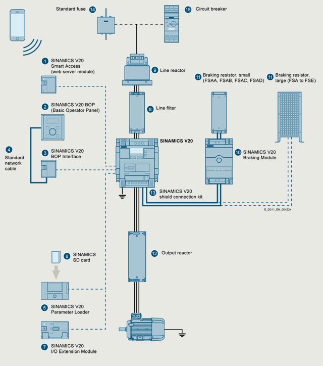
SINAMICS V20 converter and accessories
Accessories | ||
|---|---|---|
1 |
SINAMICS V20 Smart Access |
Wireless commissioning, operation, and diagnostics with mobile device or laptop using web server module |
2 |
SINAMICS V20 BOP |
|
3 |
SINAMICS V20 BOP Interface |
|
4 |
Standard network cable |
|
5 |
SINAMICS V20 Parameter Loader |
|
6 |
SINAMICS SD card |
|
7 |
SINAMICS V20 I/O Extension Module |
|
8 |
Line filter |
Improved EMC characteristics |
9 |
Line reactor |
|
10 |
SINAMICS V20 Braking Module |
|
11 |
Braking resistor |
|
12 |
Output reactor |
For longer motor cable
|
13 |
Shield connection kit |
|
14 |
Standard fuse |
Recommended fuse corresponding to the IEC/UL standard |
15 |
Circuit breaker |
Recommended circuit breaker corresponding to the IEC/UL standard |
Функции
Feature |
Comment |
|---|---|
Connection and application macros |
Sets groups of parameters to simplify commissioning
|
Keep Running Mode |
Single-parameter setting for a mode which keeps the motor going – enables
|
ECO mode |
Economy mode – searches for most efficient rated point |
Hibernation mode |
Intelligent economy mode in idle state |
PID controller |
Integrated PID controller with auto-tuning function |
Kinetic buffering (Vdc_min controller) |
Retention of minimal DC voltage through regenerative energy for continued operation |
Vdc_max controller |
Automatic change of ramp down time/braking time |
Imax controller |
Automatic change of ramp up time to avoid overcurrent |
Automatic restart |
Automatic restart of drive once the power has been restored following a power failure. All faults are acknowledged automatically and the drive is switched on again |
Flying restart |
Allows the converter to be switched to a rotating motor |
Energy consumption monitoring |
Displays a simple estimate of energy or cost saved against use of a line-connected motor |
50/60 Hz adaptation |
Easy selection of operation with 50 Hz (Europe, Asia) / 60 Hz (USA) |
V/f and V2/f |
V/f: perfectly suitable for almost any application in which the speed of asynchronous (induction) motors is to be changed V2/f: suited to loads with quadratic load curves, e.g. turbo machines such as pumps and fans |
FCC |
Maintains motor flux current for improved efficiency |
Programmable V/f coordinates |
Freely adjusts the V/f characteristics, e.g. torque behavior of the synchronous motor |
JOG |
Moves the motor to test the direction or moves the load to specific position. When the BOP switches to JOG mode, pressing the start button of the BOP will run the motor up to the JOG frequency. |
DC braking |
Stops the motor which runs at constant speed and only comes to a standstill in longer time intervals, e.g. centrifuges, saws, grinding machines and conveyor belts |
Mechanical holding brake control |
The motor holding brake prevents the motor from undesirable turning when the converter is switched off. The converter has an internal logic to control an external motor holding brake |
USS |
Universal Serial Interface Protocol |
Modbus RTU |
Modbus RTU communication available via the RS485 link |
Super torque mode |
Big torque boost for starting high-inertia applications |
Hammer start mode |
A number of torque pulses at start-up to start difficult or "stuck" loads |
Blockage clearing mode |
Multiple-reverse function to clear blocked pumps |
Simple parameter-based menu on internal or external BOPs |
Easy selection for displaying values, editing parameters, converter setup |
Simple text menu for setup |
The parameter number will be shown as short text in the 7-segment LED display |
Motor frequency display scaling |
User settable display scaling for special applications i.e. rather than Hz, it shows application-specific values like "gallons per minute", "potatoes per hour", etc. |
Customization of parameter defaults |
Customers or OEMs can set their own special "permanent" defaults which can only be deleted in special mode |
Converter status in case of a fault |
Record the fault with running data
|
List of modified parameters |
When this filter is activated, the parameter list only displays the parameters which were modified by users |
Load torque monitoring |
Detects the load torque to establish failure of the mechanical connection between motor and load machine, overload, motor blocking or no-load operation, e.g. in the event of a V-belt tear in a fan or when a load machine jams |
Phase loss detection |
Detects and protects against phase loss |
Cavitation protection |
Protects against cavitation damage to pumps |
Condensation protection |
Automatic application of DC current to motor to protect from condensation |
Frost protection |
Automatically rotates motor to stop fluids freezing when temperature falls near or below freezing e.g. for the sequential connection of multiple pumps working in one system |
Motor staging |
Automatic control and staging of several motors |
Multi-pump control 1) |
Control of up to four pumps with a frequency converter by means of optional SINAMICS V20 I/O Extension Module |
Dual ramp parameterizable |
Switchable ramps for specific applications |
Programmable fixed frequency setpoint |
16 fixed frequencies can be defined and switched by digital inputs or communication |
Drive data sets (DDS) |
3 parameter sets for the motor and load. The user can switch the parameter set to suit the motors and applications |
Command data sets (CDS) |
3 parameter sets for the setpoint and command. The user can switch the parameter set to suit the control system |
Flexible voltage boost |
Increases the output voltage to compensate resistive losses or increase the output torque |
Skippable frequency bandwidth |
Defines 1 to 4 frequencies to avoid effects of mechanical resonance and suppress frequencies within an adjustable skip frequency bandwidth |
2-wire/3-wire control |
The wide range of setting options is especially intended to allow emulation of existing control methods on the plant or system side if the converter has to be integrated into an existing application |
1) Further information on the multi-pump control can be found in the operating instructions and on the Internet at:
Интеграция
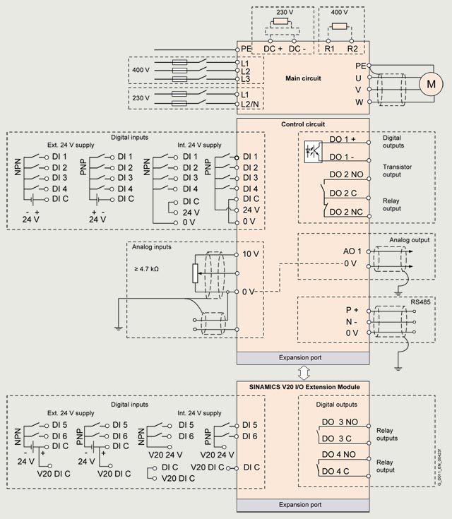
Connection example for SINAMICS V20
Заказные данные
Rated power 1) |
Rated input current |
Output current IH2) |
Fan |
Frame size |
SINAMICS V20 |
SINAMICS V20 |
|||
|---|---|---|---|---|---|---|---|---|---|
kW |
hp |
A |
A |
Article No. |
Article No. |
||||
200 ... 240 V 1 AC 4) | |||||||||
0.12 |
0.16 |
2.3 |
0.9 |
– |
FSAA |
6SL3210-5BB11-2UV1 |
6SL3210-5BB11-2BV1 |
||
0.25 |
0.33 |
4.5 |
1.7 |
– |
FSAA |
6SL3210-5BB12-5UV1 |
6SL3210-5BB12-5BV1 |
||
0.37 |
0.5 |
6.2 |
2.3 |
– |
FSAA |
6SL3210-5BB13-7UV1 |
6SL3210-5BB13-7BV1 |
||
0.55 |
0.75 |
7.7 |
3.2 |
– |
FSAB |
6SL3210-5BB15-5UV1 |
6SL3210-5BB15-5BV1 |
||
0.75 |
1 |
10 |
4.2 |
– |
FSAB |
6SL3210-5BB17-5UV1 |
6SL3210-5BB17-5BV1 |
||
1.1 |
1.5 |
14.7 |
6 |
1 |
FSAC |
6SL3210-5BB21-1UV1 |
6SL3210-5BB21-1BV1 |
||
1.5 |
2 |
19.7 |
7.8 |
1 |
FSAC |
6SL3210-5BB21-5UV1 |
6SL3210-5BB21-5BV1 |
||
2.2 |
3 |
27.2 |
11 |
1 |
FSAD |
6SL3210-5BB22-2UV1 |
6SL3210-5BB22-2BV1 |
||
3 |
4 |
32 |
13.6 |
1 |
FSAD |
6SL3210-5BB23-0UV1 |
6SL3210-5BB23-0BV1 |
||
1) Rated power of the 230 V 1 AC devices based on the output current IH. The output current IH is based on the duty cycle for high overload (HO): 150 % IH for 60 s within a cycle time of 300 s.
2) The output current IH is based on the duty cycle for high overload (HO): 150 % IH for 60 s within a cycle time of 300 s.
3) EN 61800-3 Category C1, 1st environment (residential, commercial). Max. shielded motor cable length 5 m for frame sizes FSAA, FSAB, and FSAD, and 10 m for frame size FSAC - with or without external line filter.
4) Single-phase devices can also be connected to two phases of a 3-phase 230 V power supply system. You can find detailed information here:
Rated power 1) |
Rated input current |
Output current IL2) |
Power based on the output current IH3) |
Output current IH3) |
Fan |
Frame size |
SINAMICS V20 |
SINAMICS V20 |
||
|---|---|---|---|---|---|---|---|---|---|---|
At |
At |
|||||||||
kW |
hp |
A |
A |
kW |
hp |
A |
Article No. |
Article No. |
||
380 ... 480 V 3 AC | ||||||||||
0.37 |
0.5 |
1.7 |
1.3/1.3 |
0.37 |
0.5 |
1.3/1.3 |
– |
FSA |
6SL3210-5BE13-7UV1 |
6SL3210-5BE13-7CV1 |
0.55 |
0.75 |
2.1 |
1.7/1.7 |
0.55 |
0.75 |
1.7/1.7 |
– |
FSA |
6SL3210-5BE15-5UV1 |
6SL3210-5BE15-5CV1 |
0.75 |
1 |
2.6 |
2.2/2.2 |
0.75 |
1 |
2.2/2.2 |
– |
FSA |
6SL3210-5BE17-5UV1 |
6SL3210-5BE17-5CV1 |
1.1 |
1.5 |
4 |
3.1/3.1 |
1.1 |
1.5 |
3.1/3.1 |
1 |
FSA |
6SL3210-5BE21-1UV1 |
6SL3210-5BE21-1CV1 |
1.5 |
2 |
5 |
4.1/4.1 |
1.5 |
2 |
4.1/4.1 |
1 |
FSA |
6SL3210-5BE21-5UV1 |
6SL3210-5BE21-5CV1 |
2.2 |
3 |
6.4 |
5.6/4.8 |
2.2 |
3 |
5.6/4.8 |
1 |
FSA |
6SL3210-5BE22-2UV1 |
6SL3210-5BE22-2CV1 |
3 |
4 |
8.6 |
7.3/7.3 |
3 |
4 |
7.3/7.3 |
1 |
FSB |
6SL3210-5BE23-0UV1 |
6SL3210-5BE23-0CV1 |
4 |
5 |
11.3 |
8.8/8.24 |
4 |
5 |
8.8/8.24 |
1 |
FSB |
6SL3210-5BE24-0UV1 |
6SL3210-5BE24-0CV1 |
5.5 |
7.5 |
15.2 |
12.5/11 |
5.5 |
7.5 |
12.5/11 |
1 |
FSC |
6SL3210-5BE25-5UV1 |
6SL3210-5BE25-5CV1 |
7.5 |
10 |
20.7 |
16.5/16.5 |
7.5 |
10 |
16.5/16.5 |
1 |
FSC |
6SL3210-5BE27-5UV1 |
6SL3210-5BE27-5CV1 |
11 |
15 |
30.4 |
25/21 |
11 |
15 |
25/21 |
2 |
FSD |
6SL3210-5BE31-1UV0 |
6SL3210-5BE31-1CV0 |
15 |
20 |
38.1 |
31/31 |
15 |
20 |
31/31 |
2 |
FSD |
6SL3210-5BE31-5UV0 |
6SL3210-5BE31-5CV0 |
22 |
30 |
54/45 5) |
45/40 |
18.5 |
25 |
38/34 |
2 |
FSE |
6SL3210-5BE31-8UV0 |
6SL3210-5BE31-8CV0 |
30 |
40 |
72/54 5) |
60/52 |
22 |
30 |
45/40 |
2 |
FSE |
6SL3210-5BE32-2UV0 |
6SL3210-5BE32-2CV0 |
1) Rated power of the 400 V 3 AC devices based on the output current IL. The output current IL is based on the duty cycle for low overload (LO): 110 % IL for 60 s within a cycle time of 300 s.
2) The output current IL is based on the duty cycle for low overload (LO): 110 % IL for 60 s within a cycle time of 300 s.
3) The output current IH is based on the duty cycle for high overload (HO): 150 % IH for 60 s within a cycle time of 300 s.
4) EN 61800-3 Category C3, 2nd environment (industrial). Shielded motor cable length for frame size FSA max. 10 m, for frame sizes FSB to FSD max. 25 m and for frame size FSE max. 50 m. To achieve 25 m of shielded motor cable length, even for C2 category FSA converters, unfiltered converters with external line filters must be used.
5) Regarding the first value, the rated input current for frame size FSE is based on the duty cycle for low overload (LO), regarding the second value, the current is based on the duty cycle for high overload (HO).
Accessories
Description |
Article No. |
|
|---|---|---|
|
RS485 terminating resistor Content: 50 units |
6SL3255-0VC00-0HA0 |
|
DIN rail mounting set |
||
|
6SL3261-1BA00-0AA0 |
|
|
6SL3261-1BB00-0AA0 |
|
|
Migration mounting set Required in addition to the DIN rail mounting set for |
||
|
6SL3266-1ER00-0VA0 |
|
|
6SL3266-1EB00-0VA0 |
|
|
6SL3266-1EV00-0VA0 |
|
|
Migration mounting set for frame size FSC The operating instructions must be followed for assembly. |
6SL3266-1EW00-0VA0 |
Технические данные
SINAMICS V20 |
|
|---|---|
Power range |
230 V 1 AC: 0.12 ... 3 kW (0.16 ... 4 hp) |
Displacement factor cos φ |
≥0.95 |
Power factor λ |
0.72 |
Line voltage |
230 V 1 AC: 200 ... 240 V 1 AC (-15 ... +10 %) 1) |
Maximum output voltage |
100 % of input voltage |
Line frequency |
50 Hz/60 Hz |
Line system configuration |
|
Overload capability |
|
|
High overload (HO): |
|
Low overload (LO): High overload (HO): |
Output frequency |
0 ... 550 Hz, resolution: 0.01 Hz |
Pulse frequency |
2 ... 16 kHz |
|
Efficiency According to IEC 61800-9-2 |
95 ... 98 % |
|
Efficiency class According to IEC 61800-9-2 |
IE2 |
Programmable fixed frequency setpoints |
16 |
Analog inputs |
AI1: bipolar current/voltage mode |
|
12 bit |
Analog output |
AO1 current output |
Digital inputs |
DI1 ... DI4: isolated; for 400 V converters with optional SINAMICS V20 I/O Extension Module two additional digital inputs DI5 and DI6 |
|
15 mA |
Digital outputs |
DO1: transistor output |
Integrated interface |
|
|
RS485 |
|
USS, Modbus RTU |
Extension interface |
SINAMICS V20 BOP Interface, SINAMICS V20 Smart Access, SINAMICS V20 Parameter Loader, SINAMICS V20 I/O Extension Module (cannot be operated simultaneously with SINAMICS V20 Parameter Loader) |
Control methods | |
|
✓ |
|
✓ |
Functions | |
Easy to use | |
Automatic restart |
✓ |
Parameter cloning |
✓ |
Drive data sets (DDS) |
✓ (3) |
Command data sets (CDS) |
✓ (3) |
JOG |
✓ |
Pre-configured connection macros and application macros |
✓ |
Simple parameter-based menu on internal or external SINAMICS V20 BOP |
✓ |
Simple text menu for setup |
✓ |
USS |
✓ |
Modbus RTU |
✓ |
Motor frequency display scaling |
✓ |
Customization of parameter defaults |
✓ |
Energy consumption monitoring |
✓ |
List of modified parameters |
✓ |
Converter status in case of a fault |
✓ |
Application | |
Keep Running Mode |
✓ |
Flying restart |
✓ |
PID controller |
✓ |
Kinetic buffering (Vdc_min controller) |
✓ |
Skippable frequency bandwidth |
4 |
Braking functions |
|
|
✓ |
|
✓ |
|
✓ |
2-wire/3-wire control |
✓ |
Mechanical holding brake control |
✓ |
Super torque mode |
✓ |
Hammer start mode |
✓ |
Blockage clearing mode |
✓ |
Hibernation mode |
✓ |
Motor staging |
✓ |
|
Multi-pump control 2) (for 400 V converters with optional SINAMICS V20 I/O Extension Module) |
✓ |
Dual ramp parameterizable |
✓ |
Wobble function |
✓ |
BICO function |
✓ |
Slip compensation |
✓ |
Protection | |
DC link voltage control |
✓ |
Load torque monitoring |
✓ |
Phase loss detection |
✓ |
Cavitation protection |
✓ |
Condensation protection |
✓ |
Frost protection |
✓ |
Control | |
ECO mode |
✓ |
Vdc_max controller |
✓ |
Imax controller |
✓ |
Programmable V/f coordinates |
✓ |
Flexible voltage boost |
✓ |
50/60 Hz adaptation |
✓ |
1) Single-phase devices can also be connected to two phases of a 3-phase 230 V power supply system. You can find more information here:
2) More information on the multi-pump control can be found in the operating instructions and on the internet at:
www.siemens.com/sinamics-v20/documentation
General technical specifications | ||||||||||
|---|---|---|---|---|---|---|---|---|---|---|
Degree of protection |
IP20 |
|||||||||
Mounting |
Wall mounting, side-by-side mounting, push-through mounting for FSB, FSC, FSD, and FSE |
|||||||||
Ambient temperature |
||||||||||
|
-10 ... +40 °C (14 ... 104 °F) without derating |
|||||||||
|
-40 ... +70 °C (-40 ... +158 °F) |
|||||||||
Relative humidity |
95 % (non-condensing) |
|||||||||
Cooling |
||||||||||
|
Convection cooling |
|||||||||
|
Power electronics cooled using heat sinks with external fan |
|||||||||
Installation altitude |
Up to 4000 m (13124 ft) above sea level |
|||||||||
Motor cable length |
||||||||||
|
||||||||||
|
50 m (164 ft) |
|||||||||
|
100 m (328 ft) |
|||||||||
|
||||||||||
|
25 m (82 ft) |
|||||||||
|
50 m (164 ft) |
|||||||||
|
||||||||||
|
200 m (656 ft) (shielded and unshielded) |
|||||||||
|
150 m (492 ft) (shielded and unshielded) for frame sizes FSA to FSD |
|||||||||
Vibration load |
||||||||||
|
5 ... 9 Hz: Deflection, 3.5 mm |
|||||||||
|
Area of application IIa |
|||||||||
Shock load |
||||||||||
|
Area of application II |
|||||||||
FSAA |
FSAB |
FSAC |
FSAD |
FSA |
FSA |
FSB |
FSC |
FSD |
FSE |
|
Dimensions | ||||||||||
|
68 (2.68) |
68 (2.68) |
90.8 (3.57) |
136.6 (5.38) |
90 (3.54) |
90 (3.54) |
140 (5.51) |
184 (7.24) |
240 (9.45) |
245 (9.65) |
|
142 (5.59) |
142 (5.59) |
160.9 (6.33) |
176.5 (6.95) |
150 (5.91) |
166 (6.54) |
160 (6.3) |
182 (7.17) |
206.5 (8.13) |
264.5 (10.41) |
|
107.8 (4.24) |
127.8 (5.03) |
147 (5.79) |
158.8 (6.25) |
145.5 (5.73) |
145.5 (5.73) |
164.5 (6.48) |
169 (6.65) |
172.5 (6.79) |
209 (8.23) |
Weight, approx. | ||||||||||
| ||||||||||
|
0.6 kg (1.32 lb) |
0.8 kg (1.76 lb) |
1.2 kg (2.65 lb) |
1.9 kg (4.19 lb) |
– |
– |
– |
– |
– |
– |
|
0.7 kg (1.54 lb) |
0.9 kg (1.98 lb) |
1.4 kg (3.09 lb) |
2.2 kg (4.85 lb) |
– |
– |
– |
– |
– |
– |
| ||||||||||
|
– |
– |
– |
– |
0.9 kg (1.98 lb) |
1,0 kg (2.21 lb) |
1.6 kg (3.53 lb) |
5.5 kW: 2.4 kg (5.29 lb) |
11 kW: 3.7 kg (8.16 lb) |
18.5 kW: 6.2 kg (13.7 lb) |
|
– |
– |
– |
– |
1,0 kg (2.21 lb) |
1.1 kg (2.43 lb) |
1.8 kg (3.97 lb) |
5.5 kW: 2.6 kg (5.73 lb) |
11 kW: 4.1 kg (9.04 lb) |
18.5 kW: 6.8 kg (15,0 lb) |
Mounting clearance, min. |
||||||||||
|
100 mm (3.94 in) |
|||||||||
|
100 mm (3.94 in) |
|||||||||
|
0 mm |
|||||||||
Certificates of suitability |
cULus, CE, UKCA, RCM, KC |
|||||||||
Environmental classes |
Pollution class: 3S2 |
|||||||||
CE marking, according to |
European Low-Voltage Directive (EN 61800‑5‑1/EN 60204-1), ecodesign requirements of the EU Directive 2019/1781 and European EMC Directive (EN 61800‑3) |
|||||||||
UL marking, according to |
UL508C |
|||||||||
EMC standards, radiated emissions and disturbance voltage (conducted emissions) |
||||||||||
|
|
|||||||||
|
|
|||||||||
|
|
|||||||||
Note |
The EMC product standard EN 61800‑3 does not apply directly to a frequency converter but to a PDS (Power Drive System), which covers the complete circuitry, motor and cables in addition to the converter. The converters themselves are in general not subject to marking in accordance with the EMC directive. |
|||||||||
1) To achieve 25 m (82 ft) shielded motor cable lengths with FSA frame size converters, unfiltered converters with external line filters have to be used.
Environmental Product Declaration (EPD)
Environmental Product Declarations (EPD) are available as PDFs for this product.
The EPD PDF provides brief and concise information about the ecological properties of a product.
You can find more information on the internet at:
Чертеж
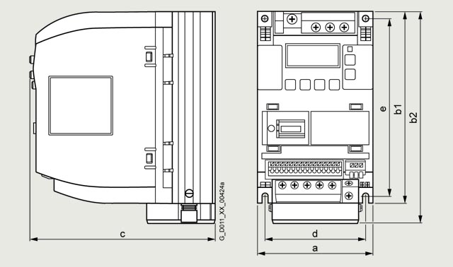
Frame size |
Dimensions |
Drilling dimensions |
||||
|---|---|---|---|---|---|---|
a (width) |
b1 (height) |
b2 (height) |
c (depth) |
d |
e |
|
FSAA |
68 (2.68) |
142 (5.59) |
– |
107.8 (4.24) |
58 (2.28) |
132 (5.2) |
FSAB |
68 (2.68) |
142 (5.59) |
– |
127.8 (5.03) |
58 (2.28) |
132 (5.2) |
FSAC |
90.8 (3.57) |
– |
160.9 (6.33) |
147 (5.79) |
79 (3.11) |
140 (5.51) |
FSAD |
136.6 (5.38) |
– |
176.5 (6.95) |
158.8 (6.25) |
122 (4.8) |
159 (6.26) |
FSA |
90 (3.54) |
150 (5.91) |
166 (6.54) |
145.5 (5.73) |
79 (3.11) |
140 (5.51) |
FSB |
140 (5.51) |
– |
160 (6.3) |
164.5 (6.48) |
127 (5) |
135 (5.31) |
FSC |
184 (7.24) |
– |
182 (7.17) |
169 (6.65) |
170 (6.69) |
140 (5.51) |
FSD |
240 (9.45) |
– |
206.5 (8.13) |
172.5 (6.79) |
223 (8.78) |
166 (6.54) |
FSE |
245 (9.65) |
– |
264.5 (10.41) |
209 (8.23) |
228 (8.98) |
206 (8.11) |
Frame size |
Mounting clearance, min. |
||
|---|---|---|---|
Top |
Bottom |
Side |
|
FSAA, FSAB, FSAC, FSAD |
100 (3.94) |
100 (3.94) |
0 |
FSA without fan |
100 (3.94) |
100 (3.94) |
0 |
FSA with fan |
100 (3.94) |
85 (3.35) |
0 |
FSB to FSE |
100 (3.94) |
100 (3.94) |
0 |
Дальнейшая информация
Identification link according to IEC 61406 for SINAMICS V20
The ID link contains the article and serial number of the product. As a QR code, it replaces the previous data matrix code on the nameplate and takes you with the URL directly to a product information page on the internet with access to the technical documentation, data sheet, certificates, FAQs, product notifications, and catalogs. Paper package inserts become superfluous since the information is available electronically directly via the QR code, even years later. In this way, we are making a valuable contribution to the preservation of our environment. You don't need an additional app. Simply scan the QR code with your smartphone or tablet. According to IEC 61406, the QR code of an ID link is marked with a frame and a triangle at the bottom right.
With their globally unique identifiers, Siemens products are ready for Industry 4.0.
The ID serves as a connection to the administration shell with which modules of the digital twin can be provided.
Detailed information on SINAMICS V20, the latest technical documentation (brochures, dimensional drawings, certificates, manuals and operating instructions) is available on the internet at:
www.siemens.com/sinamics-v20
In addition, the Siemens Product Configurator can be used on the internet. The Siemens Product Configurator can be found in SiePortal at the following address:
www.siemens.com/spc
Environmental Product Declaration (EPD)
Environmental Product Declarations (EPD) are available as PDFs for this product.
The EPD PDF provides brief and concise information about the ecological properties of a product.
You can find more information on the internet at: