




















Обзор
The 3RS2 temperature monitoring relays can be used to measure temperatures in solid, liquid and gas media. The temperature is measured by means of sensors in the medium, analyzed by the device and monitored for overshooting, undershooting or being within a specified range (window function).
The family comprises an analog multi-function device which can be set using DIP switches and potentiometers, and digital devices which can be parameterized via an intuitive LCD display. The digital device is also available as a version with IO-Link.
All 3RS26 digital devices, including the 3RS28 versions with IO‑Link, come with Safety certification according to IEC 61508/IEC 62061 or ISO 13849 up to SIL 1/PL c as well as EN 14597 for heat generating systems and EN 50156 for burners.
Furthermore, the functionality of the 3RS26/3RS28 digital devices can be expanded using a 3RS29 sensor expansion module with two additional resistance sensors, e.g. for monitoring 3-phase motors or transformers.
The 3RS29 sensor expansion module also features an additional relay for outputting the sensor status, and an additional analog input 4 to 20 mA. This analog input allows ATEX applications to be implemented when using an intrinsically safe temperature sensor or other appropriate type of protection. The 3RS29 is connected wirelessly via a SIL 1-certified infrared communications interface.
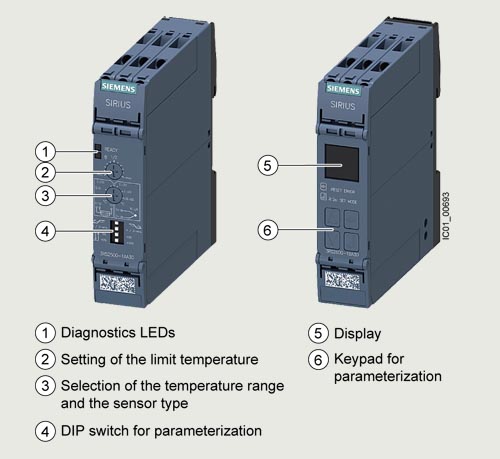
SIRIUS 3RS2 temperature monitoring relays
More information | |
|---|---|
Homepage, see www.siemens.com/sirius-monitoring-relays |
TIA Selection Tool Cloud (TST Cloud), see www.siemens.com/tstcloud/?node=SIRIUSRelais |
SiePortal, see www.siemens.com/product_catalog_siep?3RS2 |
Conversion tool, see www.siemens.com/conversion-tool |

Video: Temperature monitoring with SIRIUS relays at a glance
Analog multi-function devices
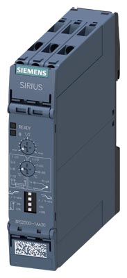
SIRIUS 3RS25 analog multi-function device
The analog multi-function device is parameterized using DIP switches and potentiometers. The device can be used to monitor a sensor with a limit value for overshoot or undershoot. The most common temperature ranges with Pt100 resistance sensors or type J or K thermocouples can be used for this purpose. This device can therefore also be used as a compact, easy-to-adjust two-point controller. The relay CO contact output enables loads to be switched directly. The NC contact can optionally be used as a signaling contact.
Digital devices (1 sensor)
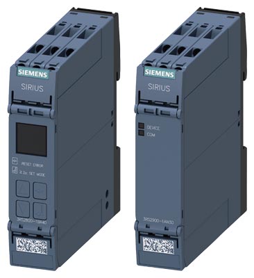
SIRIUS 3RS26 digital device (1 sensor) with 3RS29 sensor expansion module
The SIRIUS 3RS26 digital device with display enables sensors with two limit values to be monitored using all common resistance sensors and thermocouples.
The additional limit value means that, in addition to overshoot and undershoot, an additional warning value can be output to the relay outputs. Alternatively, the second monitoring value can also be used to implement range monitoring. The digital devices can thus also be used as compact two-step or three-step controllers, with manual RESET or remote RESET.
Thanks to Safety certifications, this device can be used in a wide range of applications.
The functionality of the SIRUS 3RS26 and 3RS28 digital devices can be expanded wirelessly with the sensor expansion module via a SIL 1-certified infrared communications interface. This combination then features three sensors and is designed for monitoring large 3-phase motors and transformers. It goes without saying that the additional sensors can also be used for other applications.
Digital devices (1 sensor) for IO-Link
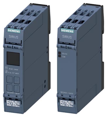
SIRIUS 3RS28 digital device (1 sensor) for IO-Link with 3RS29 sensor expansion module
The 3RS28 digital temperature monitoring relays for IO-Link feature an IO-Link communications interface in addition to a display. They include all functions of the 3RS26 digital device and can also be operated on L+/L- as a stand-alone installation with 24 V DC.
Note:
The IO-Link devices can be reset on the display or via IO‑Link.
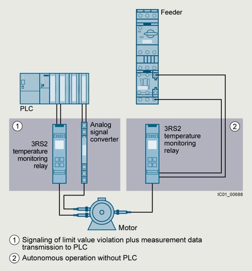
Conventional temperature monitoring relays
Notes:
Devices required for communication via IO-Link:
- Any controller that supports IO-Link (e.g. ET 200SP with CPU or S7-1200), see Catalog ST 70.
- IO‑Link master (e.g. CM 4xIO-Link for SIMATIC ET 200SP or SM 1278 for S7-1200).
Each monitoring relay requires an IO‑Link channel.
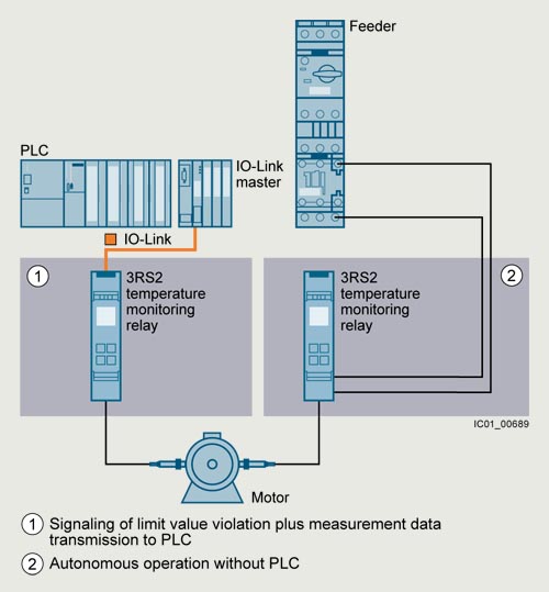
Temperature monitoring relays for IO-Link
Notes on security
In order to protect plants, systems, machines and networks against cyber threats, it is necessary to implement – and continuously maintain – a holistic, state-of-the-art industrial cybersecurity concept. Siemens products and solutions represent one component of such a concept.
For more information on industrial cybersecurity, see www.siemens.com/cybersecurity-industry.
Article number scheme
Product versions |
Article number |
|||||||||||
|---|---|---|---|---|---|---|---|---|---|---|---|---|
Temperature monitoring relays |
3RS2 |
❑ |
0 |
0 |
- |
❑ |
❑ |
❑ |
❑ |
0 |
||
Device type |
e.g. 5 = analogically adjustable |
❑ |
||||||||||
Connection type |
Screw terminals |
1 |
||||||||||
Spring-loaded terminals (push-in) |
2 |
|||||||||||
Number of CO contacts |
e.g. A = 1 CO contact, B = 2 CO contacts |
❑ |
||||||||||
Rated control supply voltage |
A = 24 V AC/DC, W = 24 ... 240 V AC/DC |
❑ |
||||||||||
Type of rated control supply voltage |
3 = AC/DC, 4 = DC |
❑ |
||||||||||
Example |
3RS2 |
5 |
0 |
0 |
- |
1 |
A |
A |
3 |
0 |
||
Note:
The article number scheme shows an overview of product versions for better understanding of the logic behind the article numbers.
For your orders, please use the article numbers quoted in the selection and ordering data.
Особенности
- Customary screw and spring-loaded terminals for quick and reliable wiring
- Reduced space requirement in the control cabinet thanks to a consistent width of 22.5 mm
- Easy parameterization thanks to new display and intuitive operating concept
- Reduced stock keeping and logistics thanks to heavily reduced device variance
- Cost savings thanks to additional scalable functionality with integrated infrared interface
- Communication via IO-Link for 3RS28
- Global applicability and exportability thanks to compliance with international standards and certifications
- Problem-free use in a wide range of applications thanks to Safety bundle with certification according to SIL 1/PL c, ATEX, EN 14597 for heat generating systems and EN 50156 for burners
- All versions with removable terminals
- All versions with screw or spring-loaded terminals with push-in functionality
Область применения
The SIRIUS 3RS2 temperature monitoring relays can be used in almost any application in which temperature overshoot or undershoot is not permitted, e.g. in the monitoring of set temperature limits and the output of alarm messages for:
- Simple and compact two-point control
- Motor and system protection
- Control cabinet temperature monitoring
- Freeze monitoring
- Temperature limits for process variables e.g. in the packaging industry or electroplating
- Controlling equipment and machines such as heating, climate and ventilation systems, solar collectors, heat pumps or warm water supplies
- Motor, bearing and gear oil monitoring
- Monitoring of coolants
Additionally for digital devices
- Simple and compact two-point or three-point control
- Burner according to EN 50156
- Thermal protectors or temperature limiters1) according to EN 14597
- ATEX explosion protection according to EN 50495
1) A 3RS29 sensor expansion module with an additional sensor is required for the function as a temperature limiter.
Технические данные
More information | |
|---|---|
Technical specifications, see |
FAQs, see |
Equipment Manual and internal circuit diagrams, see |
|
Connection of resistance-type thermometers
Two-wire measurement
When two-wire temperature sensors are used, the resistances of the sensor and wiring are added. The resulting systematic error must be taken into account when the evaluation unit is calibrated. A jumper must be clamped between terminals T2 and T3 for this purpose.
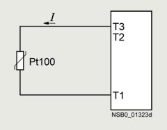
Wiring errors
The errors that are generated by the wiring comprise approximately 2.5 K/Ω. If the resistance of the cable is not known and cannot be measured, the wiring errors can also be estimated using the following table.
Temperature drift dependent on the length and cross-section of the cable with Pt100 sensors and an ambient temperature of 20 °C, in K:
Cable length in m |
Cross-section mm2 |
|||
|---|---|---|---|---|
0.5 |
0.75 |
1 |
1.5 |
|
Temperature drift in K: |
||||
0 |
0 |
0 |
0 |
0 |
10 |
1.8 |
1.2 |
0.9 |
0.6 |
25 |
4.5 |
3.0 |
2.3 |
1.5 |
50 |
9.0 |
6.0 |
4.5 |
3.0 |
75 |
13.6 |
9.0 |
6.8 |
4.5 |
100 |
18.1 |
12.1 |
9.0 |
6.0 |
200 |
36.3 |
24.2 |
18.1 |
12.1 |
500 |
91.6 |
60.8 |
45.5 |
30.2 |
Example: On a Pt100 sensor with a cable length of 10 m and a conductor cross-section of 1 mm2 the temperature drift equals 0.9 K.
Three-wire measurement
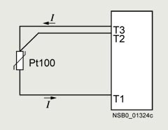
To minimize the effects of the line resistances, a three-wire circuit is often used. Using the additional cable, two measuring circuits can be formed of which one is used as a reference.
The evaluation unit can then automatically calculate the line resistance and take it into account.
Connection of thermocouples
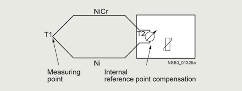
Based on the thermo-electrical effect, a differential temperature measurement will be performed between the measuring point and the evaluation unit.
This principle assumes that the evaluation unit knows the temperature at the clamping point (T2). For this reason, the 3RS2 temperature monitoring relays have an integral compensator that determines this comparison temperature and builds it into the result of the measurement. The thermal sensors and cables must therefore be insulated.
The absolute temperature is therefore calculated from the ambient temperature of the evaluation unit and the temperature difference measured by the thermocouple.
Temperature detection is therefore possible (T1) without needing to know the precise ambient temperature of the clamping point at the evaluation unit (T2).
The connecting cable is only permitted to be extended using compensating lines that are made from the same material as the thermocouple. If a different type of conductor is used, an error will result in the measurement.
For more information, see https://www.ephymess.de/en/.
Principle of operation
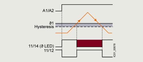
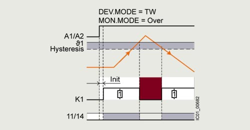
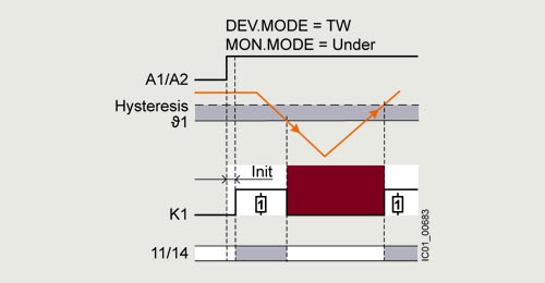
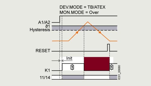
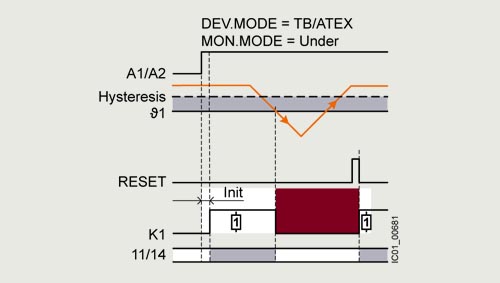
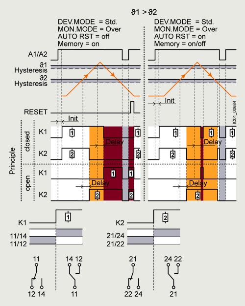
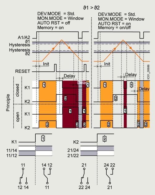
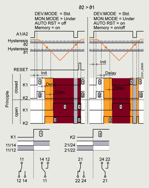
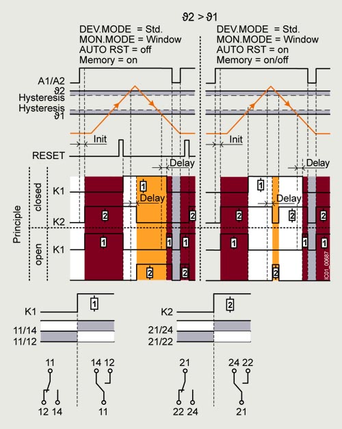
Once the temperature has reached the set threshold value ϑ1, the K1 output relay changes its switching state as soon as the set time t has elapsed (K2 responds in the same manner to ϑ2). The delay time can only be adjusted with digital units (on analog units t = 0).
When automatic RESET (AUTO RST) is set, the relays return to their original state as soon as the temperature reaches the set hysteresis value.
The memory function (MEMORY) allows the status to be saved even in the event of a voltage failure.
3RS25 analog multi-function devices
Temperature overshoot
Temperature undershoot
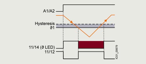
3RS26, 3RS28 digital devices (1 sensor) with Safety function
Temperature monitors according to EN 14597
Temperature overshoot
Temperature undershoot
Temperature limiters according to EN 14597/ATEX
Temperature overshoot
Temperature undershoot
3RS26, 3RS28 digital devices (1 sensor)
Temperature overshoot
Range monitoring
Temperature undershoot
Range monitoring
Characteristic curves
For resistance sensors
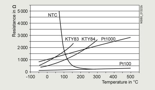
Characteristic curves for resistance sensors
The short-circuit and open-circuit detection as well as the measuring range is limited, depending on the sensor type.
Measuring ranges and switch position for analog devices in °C for Pt100 resistance sensor
Measuring range in °C |
Switch position in °C |
||||||||||
|---|---|---|---|---|---|---|---|---|---|---|---|
min. |
1/2 |
Max. |
|||||||||
0 ... +100 |
0 |
10 |
20 |
30 |
40 |
50 |
60 |
70 |
80 |
90 |
100 |
0 ... +200 |
0 |
20 |
40 |
60 |
80 |
100 |
120 |
140 |
160 |
180 |
200 |
-50 ... +50 |
-50 |
-40 |
-30 |
-20 |
-10 |
0 |
10 |
20 |
30 |
40 |
50 |
Measuring ranges for digital devices in °C for resistance sensor
Sensor type |
Short circuit |
Open circuit |
3RS26, 3RS28 |
3RS26, 3RS28 |
|---|---|---|---|---|
Pt100 |
✓ |
✓ |
-50 ... +750 |
-58 ... +1 382 |
Pt1000 |
✓ |
✓ |
-50 ... +500 |
-58 ... +932 |
KTY83-110 |
✓ |
✓ |
-50 ... +175 |
-58 ... +347 |
KTY84 |
✓ |
✓ |
-40 ... +300 |
-40 ... +572 |
NTC1) |
✓ |
-- |
+80 ... +160 |
+176 ... +320 |
✓ Detection possible
-- Detection not possible
1) NTC type: B57227-K333-A1 (100 °C: 1.8 kΩ; 25 °C: 32.762 kΩ).
For thermocouples
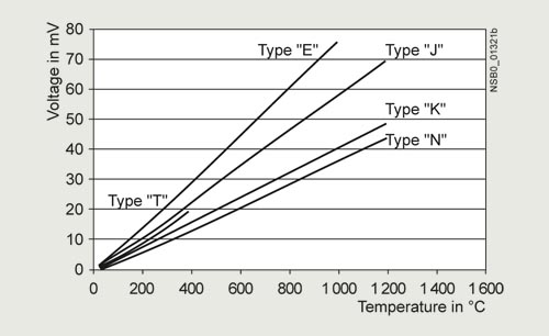
Characteristic curves for thermocouples J, K, T, E, and N

Characteristic curves for thermocouples S, R and B
Measuring ranges and switch position for analog devices in °C for thermocouple types J and K
Measuring range in °C |
Switch position in °C |
||||||||||
|---|---|---|---|---|---|---|---|---|---|---|---|
min. |
1/2 |
Max. |
|||||||||
0 ... +200 |
0 |
20 |
40 |
60 |
80 |
100 |
120 |
140 |
160 |
180 |
200 |
0 ... +600 |
0 |
60 |
120 |
180 |
240 |
300 |
360 |
420 |
480 |
540 |
600 |
+500 ... +1 000 |
500 |
550 |
600 |
650 |
700 |
750 |
800 |
850 |
900 |
950 |
1 000 |
Measuring ranges for digital devices in °C/°F for thermocouples
Sensor type |
Short circuit |
Open circuit |
3RS26, 3RS28 |
3RS26, 3RS28 |
|---|---|---|---|---|
J |
-- |
✓ |
-99 ... +1 200 |
-146.2 ... +2 192 |
K |
-- |
✓ |
-99 ... +1 350 |
-146.2 ... +2 462 |
T |
-- |
✓ |
-99 ... +400 |
-146.2 ... +752 |
E |
-- |
✓ |
-99 ... +999 |
-146.2 ... +1 830.2 |
N |
-- |
✓ |
+99 ... +1 300 |
-146.2 ... +2 372 |
S |
-- |
✓ |
0 ... +1 750 |
+32 ... +3 182 |
R |
-- |
✓ |
0 ... +1 750 |
+32 ... +3 182 |
B |
-- |
✓ |
+400 ... +1 800 |
+752 ... +3 272 |
✓ Detection possible
-- Detection not possible
Article number |
3RS2500-....0 |
3RS2600-....0 |
3RS2800-....0 |
3RS2900-....0 |
||
|---|---|---|---|---|---|---|
General technical data |
||||||
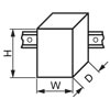
Width x Height x Depth |
mm |
22.5 × 100 × 90 |
||||
ambient temperature |
||||||
|
°C |
-25 ... +60 |
||||
|
°C |
-40 ... +85 |
||||
|
°C |
-40 ... +85 |
||||
protection class IP |
20 |
|||||
mounting position |
any |
|||||
fastening method |
screw and snap-on mounting onto 35 mm DIN rail |
|||||
Auxiliary circuit |
||||||
type of voltage |
AC/DC |
DC |
AC/DC |
|||
operating range factor control supply voltage rated value |
||||||
|
0.85 ... 1.1 |
-- |
0.85 ... 1.1 |
|||
|
0.85 ... 1.1 |
-- |
0.85 ... 1.1 |
|||
|
0.85 ... 1.1 |
0.7 ... 1.25 |
0.85 ... 1.1 |
|||
operating frequency rated value |
Hz |
50 ... 60 |
||||
number of measuring circuits |
1 |
3 |
||||
number of CO contacts for auxiliary contacts |
1 |
2 |
0 |
|||
product component removable terminal for auxiliary and control circuit |
Yes |
|||||
product function |
||||||
|
Yes |
-- |
||||
|
No |
Yes |
||||
|
No |
Yes |
||||
ATEX |
||||||
certificate of suitability relating to ATEX |
No |
Yes, with 3RS29 sensor expansion module |
Yes, with 3RS26/3RS28 digital device |
|||
Safety Integrity Level (SIL) according to IEC 62061 |
-- |
SIL 1 |
||||
performance level (PL) according to ISO 13849-1 |
-- |
PL c |
||||
Article number |
3RS2500-1...0 |
3RS2500-2...0 |
||
|---|---|---|---|---|
type of electrical connection |
screw-type terminals |
spring-loaded terminals (push-in) |
||
tightening torque |
N·m |
0.6 ... 0.8 |
-- ... -- |
|
type of connectable conductor cross-sections |
||||
|
1x (0.5 ... 4 mm²), 2x (0.5 ... 2.5 mm²) |
1x (0.5 ... 4 mm²) |
||
|
||||
|
-- |
0.5 ... 4 mm² |
||
|
1x (0.5 ... 4 mm²), 2x (0.5 ... 1.5 mm²) |
1x (0.5 ... 2.5 mm²) |
||
|
||||
|
1x (20 ... 12), 2x (20 ... 14) |
1x (20 ... 12) |
||
|
-- |
20 ... 12 |
||