


















Обзор
Equipped with the utmost functionality, the SIRIUS 3RW55 High Performance soft starters confidently handle even difficult starting and stopping operations. Thanks to innovative torque control, the device can be used for drives with an output of between 5.5 kW and 1 200 kW (at 400 V).
The functions have been specially designed to offer maximum user friendliness. The detachable HMI (with color display, local interface and slot for micro SD memory card) and plug-in communications modules (PROFINET, PROFIBUS, EtherNet/IP and Modbus) provide maximum flexibility.
With their modern hybrid switching technology, the SIRIUS 3RW55 soft starters offer efficient switching for long-term, energy-saving use.
More information | |
|---|---|
Homepage, see www.siemens.com/sirius-soft-starter |
SIRIUS Soft Starter ES (TIA Portal), see |
SiePortal, see www.siemens.com/product_catalog_siep?3RW55 |
SIRIUS 3RW soft starter block library for SIMATIC PCS 7, see |
TIA Selection Tool Cloud (TST Cloud), see www.siemens.com/tstcloud/?node=3rw55 |
Decision support for motor start – Starting and operating three-phase asynchronous motors efficiently, see www.siemens.com/motorstart-guide |
Topic page, see |
SIRIUS Sim, see |
Simulation Tool for Soft Starters (STS), see |
Conversion tool, see www.siemens.com/conversion-tool |
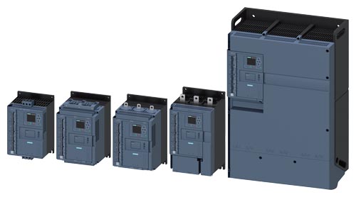
SIRIUS 3RW55 soft starters device family
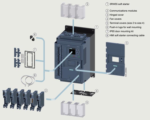
SIRIUS 3RW55 High Performance soft starters with accessories
Особенности
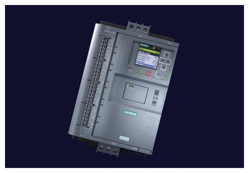
Product characteristics/function |
Performance features/benefits |
Automatic parameterization |
Extremely easy commissioning and reliability even under changing load conditions |
Hybrid switching technology and 3-phase motor control |
Minimum power loss and optimum/symmetrical motor control |
TIA integration – communications modules optional |
Efficient configuration and maximum flexibility in automation engineering |
Removable HMI with color display, local interface, slot for micro SD memory card |
Maximum flexibility with regard to user interface and intuitive menu guidance |
Pump stop and torque control |
Reduced mechanical loading and optimum pump stop control |
Certified according to ATEX/IECEx directive |
Suitable for the starting of explosion-proof motors |
System redundancy S2 |
Simple and straight-forward integration into fault-tolerant automation systems |
Direct integration in Insights Hub via the OPC UA server |
Worldwide data availability for optimal plant operation |
Технические данные
More information | |
|---|---|
Technical specifications, see |
FAQs, see |
Equipment Manual, see |
Simulation Tool for Soft Starters (STS), see |
Type |
3RW5513 |
3RW5514 |
3RW5515 |
3RW5516 |
3RW5517 |
|
|---|---|---|---|---|---|---|
Rated operational current Ie |
A |
13 |
18 |
25 |
32 |
38 |
Power electronics | ||||||
Load rating rated operational current Ie |
||||||
IEC + UL/CSA individual mounting at 40/50/60 °C, AC‑53a |
A |
13/11.5/10.5 |
18/15.9/13.8 |
25/22.3/19.6 |
32/28.4/26 |
38/33.5/30.5 |
Permissible rated motor current and starts/h | ||||||
Normal starting (CLASS 10A) |
||||||
Rated motor current IM; Tu = 40/50/60 °C |
A |
13/11.5/10.5 |
18/15.9/13.8 |
25/22.3/19.6 |
32/28.4/26 |
38/33.5/30.5 |
|
||||||
|
1/h |
43 |
43 |
43 |
43 |
43 |
|
1/h |
18 |
18 |
18 |
18 |
18 |
|
||||||
|
1/h |
28 |
28 |
28 |
28 |
28 |
|
1/h |
10 |
10 |
10 |
10 |
10 |
Normal starting (CLASS 10E) |
||||||
Rated motor current IM; Tu = 40/50/60 °C |
A |
13/11.5/10.5 |
18/15.9/13.8 |
25/22.3/19.6 |
32/28.4/26 |
38/33.5/30.5 |
|
||||||
|
1/h |
21 |
21 |
21 |
21 |
21 |
|
1/h |
8 |
8 |
8 |
8 |
8 |
|
||||||
|
1/h |
13 |
13 |
13 |
13 |
13 |
|
1/h |
4 |
4 |
4 |
4 |
4 |
Heavy starting (CLASS 20E) |
||||||
Rated motor current IM; Tu = 40/50/60 °C |
A |
13/11.5/10.5 |
18/15.9/13.8 |
25/22.3/19.6 |
29.6/27.2/23.6 |
33.5/30.5/27.5 |
|
||||||
|
1/h |
10 |
10 |
10 |
10 |
10 |
|
1/h |
4 |
4 |
4 |
4 |
4 |
|
||||||
|
1/h |
7 |
7 |
7 |
7 |
7 |
|
1/h |
2.5 |
2.5 |
2.5 |
2.5 |
2.5 |
Heavy starting (CLASS 30E) |
||||||
Rated motor current IM; Tu = 40/50/60 °C |
A |
13/11.5/10.5 |
18/15.9/13.8 |
25/22.3/19.6 |
26/23.6/21.2 |
29/26/23 |
|
||||||
|
1/h |
7 |
7 |
7 |
7 |
7 |
|
1/h |
3 |
3 |
3 |
3 |
3 |
|
||||||
|
1/h |
4 |
4 |
4 |
4 |
4 |
|
1/h |
1.8 |
1.8 |
1.8 |
1.8 |
1.8 |
Adjustable rated motor current IM |
||||||
|
A |
2.5/13 |
3.5/18 |
5/25 |
6.5/32 |
7.5/38 |
|
A |
4.3/22.5 |
6.1/31.1 |
8.7/43.3 |
11.3/55.4 |
13/65.8 |
Type |
3RW5521 |
3RW5524 |
3RW5525 |
3RW5526 |
3RW5527 |
|
|---|---|---|---|---|---|---|
Rated operational current Ie |
A |
25 |
47 |
63 |
77 |
93 |
Power electronics | ||||||
Load rating rated operational current Ie |
||||||
IEC + UL/CSA individual mounting at 40/50/60 °C, AC‑53a |
A |
25/22.3/19.6 |
47/41.6/36.2 |
63/55.5/50.5 |
77/68/62 |
93/82.5/75.5 |
Permissible rated motor current and starts/h | ||||||
Normal starting (CLASS 10A) |
||||||
Rated motor current IM; Tu = 40/50/60 °C |
A |
25/22.3/19.6 |
47/41.6/36.2 |
63/55.5/50.5 |
77/68/62 |
93/82.5/75.5 |
|
||||||
|
1/h |
43 |
43 |
43 |
43 |
43 |
|
1/h |
18 |
18 |
18 |
18 |
18 |
|
||||||
|
1/h |
28 |
28 |
28 |
28 |
28 |
|
1/h |
10 |
10 |
10 |
10 |
10 |
Normal starting (CLASS 10E) |
||||||
Rated motor current IM; Tu = 40/50/60 °C |
A |
25/22.3/19.6 |
47/41.6/36.2 |
63/55.5/50.5 |
77/68/62 |
93/82.5/75.5 |
|
||||||
|
1/h |
21 |
21 |
21 |
21 |
21 |
|
1/h |
8 |
8 |
8 |
8 |
8 |
|
||||||
|
1/h |
13 |
13 |
13 |
13 |
13 |
|
1/h |
4 |
4 |
4 |
4 |
4 |
Heavy starting (CLASS 20E) |
||||||
Rated motor current IM; Tu = 40/50/60 °C |
A |
25/22.3/19.6 |
47/41.6/36.2 |
63/55.5/50.5 |
77/68/62 |
93/82.5/75.5 |
|
||||||
|
1/h |
10 |
10 |
10 |
10 |
10 |
|
1/h |
4 |
4 |
4 |
4 |
4 |
|
||||||
|
1/h |
7 |
7 |
7 |
7 |
7 |
|
1/h |
2.5 |
2.5 |
2.5 |
2.5 |
2.5 |
Heavy starting (CLASS 30E) |
||||||
Rated motor current IM; Tu = 40/50/60 °C |
A |
25/22.3/19.6 |
43.4/38/34.4 |
53/48/43 |
68/62/56 |
82.5/75.5/65 |
|
||||||
|
1/h |
7 |
7 |
7 |
7 |
7 |
|
1/h |
3 |
3 |
3 |
3 |
3 |
|
||||||
|
1/h |
4 |
4 |
4 |
4 |
4 |
|
1/h |
1.8 |
1.8 |
1.8 |
1.8 |
1.8 |
Adjustable rated motor current IM |
||||||
|
A |
5/25 |
10/47 |
13/63 |
16/77 |
19/93 |
|
A |
8.7/43.3 |
17.3/81.4 |
22.5/109 |
27.7/133 |
32.9/161 |
Type |
3RW5534 |
3RW5535 |
3RW5536 |
|
|---|---|---|---|---|
Rated operational current Ie |
A |
113 |
143 |
171 |
Power electronics | ||||
Load rating rated operational current Ie |
||||
IEC + UL/CSA individual mounting at 40/50/60 °C, AC‑53a |
A |
113/101/89 |
143/128/118 |
171/153/141 |
Permissible rated motor current and starts/h | ||||
Normal starting (CLASS 10A) |
||||
Rated motor current IM; Tu = 40/50/60 °C |
A |
113/101/89 |
143/128/118 |
171/153/141 |
|
||||
|
1/h |
43 |
43 |
43 |
|
1/h |
18 |
18 |
18 |
|
||||
|
1/h |
28 |
28 |
28 |
|
1/h |
10 |
10 |
10 |
Normal starting (CLASS 10E) |
||||
Rated motor current IM; Tu = 40/50/60 °C |
A |
113/101/89 |
143/128/118 |
171/153/141 |
|
||||
|
1/h |
21 |
21 |
21 |
|
1/h |
8 |
8 |
8 |
|
||||
|
1/h |
13 |
13 |
13 |
|
1/h |
4 |
4 |
4 |
Heavy starting (CLASS 20E) |
||||
Rated motor current IM; Tu = 40/50/60 °C |
A |
109/97/85 |
128/113/103 |
141/129/117 |
|
||||
|
1/h |
10 |
10 |
10 |
|
1/h |
4 |
4 |
4 |
|
||||
|
1/h |
7 |
7 |
7 |
|
1/h |
2.5 |
2.5 |
2.5 |
Heavy starting (CLASS 30E) |
||||
Rated motor current IM; Tu = 40/50/60 °C |
A |
89/81/74 |
108/98/88 |
117/105/93 |
|
||||
|
1/h |
7 |
7 |
7 |
|
1/h |
3 |
3 |
3 |
|
||||
|
1/h |
4 |
4 |
4 |
|
1/h |
1.8 |
1.8 |
1.8 |
Adjustable rated motor current IM |
||||
|
A |
23/113 |
29/143 |
34/171 |
|
A |
39.8/195 |
50.2/247 |
58.9/296 |
Type |
3RW5543 |
3RW5544 |
3RW5545 |
3RW5546 |
3RW5547 |
3RW5548 |
|
|---|---|---|---|---|---|---|---|
Rated operational current Ie |
A |
210 |
250 |
315 |
370 |
470 |
570 |
Power electronics | |||||||
Load rating rated operational current Ie |
|||||||
IEC + UL/CSA individual mounting at 40/50/60 °C, AC‑53a |
A |
210/186/170 |
250/220/200 |
315/279/255 |
370/328/300 |
470/416/380 |
570/504/460 |
Permissible rated motor current and starts/h | |||||||
Normal starting (CLASS 10A) |
|||||||
Rated motor current IM; Tu = 40/50/60 °C |
A |
210/186/170 |
250/220/200 |
315/279/255 |
370/328/300 |
470/416/380 |
570/504/460 |
|
|||||||
|
1/h |
43 |
43 |
43 |
43 |
40 |
20 |
|
1/h |
18 |
18 |
18 |
18 |
17 |
6 |
|
|||||||
|
1/h |
28 |
28 |
28 |
28 |
26 |
9 |
|
1/h |
10 |
10 |
10 |
10 |
10 |
1 |
Normal starting (CLASS 10E) |
|||||||
Rated motor current IM; Tu = 40/50/60 °C |
A |
210/186/170 |
250/220/200 |
315/279/255 |
370/328/300 |
470/416/380 |
551/490/445 |
|
|||||||
|
1/h |
21 |
21 |
21 |
21 |
17 |
8 |
|
1/h |
8 |
8 |
8 |
8 |
6 |
1 |
|
|||||||
|
1/h |
13 |
13 |
13 |
13 |
10 |
2 |
|
1/h |
4 |
4 |
4 |
4 |
2 |
-- |
Heavy starting (CLASS 20E) |
|||||||
Rated motor current IM; Tu = 40/50/60 °C |
A |
162/146/130 |
200/180/160 |
231/207/183 |
258/230/202 |
272/254/236 |
284/262/240 |
|
|||||||
|
1/h |
10 |
10 |
10 |
10 |
10 |
10 |
|
1/h |
4 |
4 |
4 |
4 |
4 |
4 |
|
|||||||
|
1/h |
7 |
7 |
7 |
7 |
7 |
7 |
|
1/h |
2.5 |
2.5 |
2.5 |
2.5 |
2.5 |
2.5 |
Heavy starting (CLASS 30E) |
|||||||
Rated motor current IM; Tu = 40/50/60 °C |
A |
138/122/106 |
160/140/120 |
183/159/135 |
202/174/160 |
210/190/170 |
220/200/180 |
|
|||||||
|
1/h |
7 |
7 |
7 |
7 |
7 |
7 |
|
1/h |
3 |
3 |
3 |
3 |
3 |
3 |
|
|||||||
|
1/h |
4 |
4 |
4 |
4 |
4 |
4 |
|
1/h |
1.8 |
1.8 |
1.8 |
1.8 |
1.8 |
1.8 |
Adjustable rated motor current IM |
|||||||
|
A |
42/210 |
50/250 |
63/315 |
74/370 |
94/470 |
114/570 |
|
A |
72.7/363 |
86.6/433 |
109.1/545 |
128.2/640 |
162.8/814 |
197.5/987 |
Type |
3RW5552 |
3RW5553 |
3RW5554 |
3RW5556 |
3RW5558 |
|
|---|---|---|---|---|---|---|
Rated operational current Ie |
A |
630 |
720 |
840 |
1 100 |
1 280 |
Power electronics | ||||||
Load rating rated operational current Ie |
||||||
IEC + UL/CSA individual mounting at 40/50/60 °C, AC‑53a |
A |
630/561/510 |
720/641/580 |
840/748/670 |
1 100/979/890 |
1 280/1 139/1 030 |
Permissible rated motor current and starts/h | ||||||
Normal starting (CLASS 10A) |
||||||
Rated motor current IM; Tu = 40/50/60 °C |
A |
630/561/510 |
720/641/580 |
840/748/670 |
1 100/979/890 |
1 280/1 139/1 030 |
|
||||||
|
1/h |
43 |
43 |
42 |
43 |
32 |
|
1/h |
18 |
18 |
18 |
18 |
12 |
|
||||||
|
1/h |
28 |
28 |
25 |
27 |
17 |
|
1/h |
10 |
10 |
10 |
9 |
4 |
Normal starting (CLASS 10E) |
||||||
Rated motor current IM; Tu = 40/50/60 °C |
A |
630/561/510 |
720/641/580 |
840/748/670 |
1 100/979/890 |
1 225/1 130/1 030 |
|
||||||
|
1/h |
21 |
21 |
19 |
18 |
15 |
|
1/h |
8 |
8 |
7 |
7 |
5 |
|
||||||
|
1/h |
13 |
13 |
10 |
9 |
1 |
|
1/h |
4 |
4 |
2 |
2 |
1 |
Heavy starting (CLASS 20E) |
||||||
Rated motor current IM; Tu = 40/50/60 °C |
A |
500/450/400 |
520/470/420 |
570/520/470 |
920/840/760 |
980/900/810 |
|
||||||
|
1/h |
10 |
10 |
10 |
10 |
10 |
|
1/h |
4 |
4 |
4 |
4 |
4 |
|
||||||
|
1/h |
7 |
7 |
7 |
7 |
7 |
|
1/h |
2.5 |
2.5 |
2.5 |
2.5 |
2.5 |
Heavy starting (CLASS 30E) |
||||||
Rated motor current IM; Tu = 40/50/60 °C |
A |
380/340/300 |
400/360/320 |
420/380/340 |
740/670/600 |
790/720/650 |
|
||||||
|
1/h |
7 |
7 |
7 |
7 |
7 |
|
1/h |
3 |
3 |
3 |
3 |
3 |
|
||||||
|
1/h |
4 |
4 |
4 |
4 |
4 |
|
1/h |
1.8 |
1.8 |
1.8 |
1.8 |
1.8 |
Adjustable rated motor current IM |
||||||
|
A |
114/630 |
144/720 |
168/840 |
220/1 100 |
258/1 280 |
|
A |
197.5/987 |
249.4/1 247 |
291/1 454 |
381.1/1 905 |
446.9/2 217 |
Motor feeders according to IEC with 3RV2 motor starter protectors or 3VA circuit breakers (without semiconductor protection)
Type of coordination "1", CLASS 10,
short-circuit breaking capacity Iq in kA, see table
Note:
For general recommendations on the setup of motor feeders with soft starters, see SIRIUS 3RW soft starters → Overview → Motor feeders with soft starters.
|
|
|||||||
|---|---|---|---|---|---|---|---|---|
Soft starters |
Motor starter protectors/circuit breakers |
Motor starter protectors/circuit breakers |
||||||
for 400 V systems |
for 500 V systems |
for 400 V systems |
for 500 V systems |
|||||
Q11 |
Q1 |
Iq |
Q1 |
Iq |
Q1 |
Iq |
Q1 |
Iq |
Type |
Type |
kA |
Type |
kA |
Type |
kA |
Type |
kA |
|
Type of coordination "1"
|
Standard (inline) circuit |
Inside-delta circuit |
||||||
3RW5513 |
3RV2032-4TA10 |
65 |
3RV2032-4TA10 |
18 |
3RV2032-4DA10 |
65 |
3RV2032-4DA10 |
18 |
3RW5514 |
3RV2032-4DA10 |
65 |
3RV2032-4DA10 |
15 |
3RV2032-4EA10 |
65 |
3RV2032-4EA10 |
15 |
3RW5515 |
3RV2032-4EA10 |
65 |
3RV2032-4EA10 |
15 |
3RV2032-4VA10 |
65 |
3RV2032-4VA10 |
15 |
3RW5516 |
3RV2032-4VA10 |
65 |
3RV2032-4VA10 |
10 |
3RV2032-4JA10 |
65 |
3RV2032-4JA10 |
10 |
3RW5517 |
3RV2032-4WA10 |
65 |
3RV2032-4WA10 |
10 |
3RV2032-4RA10 |
65 |
3RV2032-4RA10 |
10 |
3RW5521 |
-- |
-- |
-- |
-- |
-- |
-- |
-- |
-- |
3RW5524 |
3RV2032-4JA10 |
65 |
3RV2032-4JA10 |
10 |
3RV2032-4RA10 |
65 |
3RV2032-4RA10 |
10 |
3RW5525 |
3VA2163-7MN32-0AA0 |
65 |
3VA2163-7MN32-0AA0 |
20 |
3VA2110-7MN32-0AA0 |
65 |
3VA2110-7MN32-0AA0 |
20 |
3RW5526 |
3VA2110-7MN32-0AA0 |
65 |
3VA2110-7MN32-0AA0 |
20 |
3VA2216-7MN32-0AA0 |
65 |
3VA2216-7MN32-0AA0 |
20 |
3RW5527 |
3VA2216-7MN32-0AA0 |
15 |
3VA2216-7MN32-0AA0 |
10 |
3VA2220-7MN32-0AA0 |
15 |
3VA2220-7MN32-0AA0 |
10 |
3RW5534 |
3VA2216-7MN32-0AA0 |
65 |
-- |
-- |
3VA2220-7MN32-0AA0 |
65 |
-- |
-- |
3RW5535 |
3VA2220-7MN32-0AA0 |
65 |
-- |
-- |
3VA2325-7MN32-0AA0 |
65 |
-- |
-- |
3RW5536 |
3VA2325-7MN32-0AA0 |
30 |
3VA2325-7MN32-0AA0 |
10 |
3VA2440-7MN32-0AA0 |
30 |
3VA2440-7MN32-0AA0 |
10 |
3RW5543 |
3VA2325-7MN32-0AA0 |
65 |
3VA2325-7MN32-0AA0 |
65 |
3VA2440-7MN32-0AA0 |
65 |
3VA2440-7MN32-0AA0 |
65 |
3RW5544 |
3VA2440-7MN32-0AA0 |
65 |
3VA2440-7MN32-0AA0 |
65 |
3VA2450-7MN32-0AA0 |
65 |
3VA2450-7MN32-0AA0 |
65 |
3RW5545 |
3VA2440-7MN32-0AA0 |
65 |
3VA2440-7MN32-0AA0 |
65 |
3VA2580-6HN32-0AA0 |
65 |
3VA2580-6HN32-0AA0 |
65 |
3RW5546 |
3VA2440-7MN32-0AA0 |
65 |
3VA2440-7MN32-0AA0 |
65 |
3VA2580-6HN32-0AA0 |
65 |
3VA2580-6HN32-0AA0 |
65 |
3RW5547 |
3VA2450-7MN32-0AA0 |
65 |
3VA2450-7MN32-0AA0 |
65 |
3VA2510-6HN32-0AA0 |
65 |
3VA2510-6HN32-0AA0 |
65 |
3RW5548 |
3VA2580-6HN32-0AA0 |
65 |
3VA2580-6HN32-0AA0 |
65 |
3VA2510-6HN32-0AA0 |
65 |
3VA2510-6HN32-0AA0 |
65 |
3RW5552 |
3VA2580-6HN32-0AA0 |
65 |
3VA2580-6HN32-0AA0 |
65 |
3VA2716-7AB05-0AA0 |
65 |
3VA2716-7AB05-0AA0 |
65 |
3RW5553 |
3VA2510-6HN32-0AA0 |
65 |
3VA2510-6HN32-0AA0 |
65 |
3VA2716-7AB05-0AA0 |
65 |
3VA2716-7AB05-0AA0 |
65 |
3RW5554 |
3VA2510-6HN32-0AA0 |
65 |
3VA2510-6HN32-0AA0 |
65 |
3VA2716-7AB05-0AA0 |
65 |
3VA2716-7AB05-0AA0 |
65 |
3RW5556 |
3VA2716-7AB05-0AA0 |
65 |
3VA2716-7AB05-0AA0 |
65 |
-- |
-- |
-- |
-- |
3RW5558 |
3VA2716-7AB05-0AA0 |
65 |
3VA2716-7AB05-0AA0 |
65 |
-- |
-- |
-- |
-- |
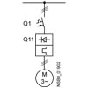
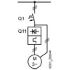
Note:
The service factor or measurement inaccuracies have been taken into account, for example, for the selection of the specified motor starter protectors/circuit breakers; the specified short-circuit breaking capacities Iq in kA are covered by combination tests. Smaller motor starter protectors/circuit breakers from the same series can be used at any time as smaller ones trip more quickly in the event of a short circuit (unchanged short-circuit breaking capacity) and thus protect the soft starter in any case. The dimensioning of the short-circuit components must match the connected three-phase motor, the short-circuit and overload requirements of the application, and the line protection for the cables used.
When using braking functions, the use of fuses is recommended to avoid the risk of false tripping of 3VA circuit breakers with electronic motor protection function during braking.
In 690 V systems, in motor feeder tests with soft starters demonstrable short-circuit breaking capacities can only be achieved with the use of fuses (Iq > 5 to 10 kA).
Motor feeders according to IEC with 3NA3 fuses
gG class full-range fuses for cable and line protection
according to IEC 60269‑2, without semiconductor protection
Type of coordination "1",
short-circuit breaking capacity Iq = 65 A
Note:
For general recommendations on the setup of motor feeders with soft starters, see SIRIUS 3RW soft starters → Overview → Motor feeders with soft starters.
|
|
|
||||||
|---|---|---|---|---|---|---|---|---|
Soft starters |
gG class fuse |
Line contactor (optional) |
gG class fuse |
Line contactor (optional) |
||||
for systems |
for systems |
for systems |
for systems |
for systems |
for systems |
for systems |
for systems |
|
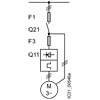
Q11 |
F1 |
Q21 |
Q21 |
F1 |
Q21 |
Q21 |
Q21 |
Q21 |
Type |
Type |
Type |
Type |
Type |
Type |
Type |
Type |
Type |
|
Type of coordination "1"
|
Standard (inline) circuit |
Inside-delta circuit |
||||||
3RW5513 |
3NA3820-6 |
3RT2025 |
3RT2025 |
3NA3820-6 |
3RT2027 |
3RT2035 |
3RT2025 |
3RT2025 |
3RW5514 |
3NA3820-6 |
3RT2026 |
3RT2027 |
3NA3820-6 |
3RT2027 |
3RT2037 |
3RT2026 |
3RT2027 |
3RW5515 |
3NA3822-6 |
3RT2027 |
3RT2037 |
3NA3822-6 |
3RT2036 |
3RT2037 |
3RT2027 |
3RT2037 |
3RW5516 |
3NA3824-6 |
3RT2035 |
3RT2037 |
3NA3824-6 |
3RT2037 |
3RT2038 |
3RT2035 |
3RT2037 |
3RW5517 |
3NA3824-6 |
3RT2035 |
3RT2037 |
3NA3824-6 |
3RT2038 |
3RT2046 |
3RT2035 |
3RT2037 |
3RW5521 |
3NA3824-6 |
3RT2027 |
3RT2037 |
3NA3824-6 |
3RT2036 |
3RT2037 |
3RT2027 |
3RT2037 |
3RW5524 |
3NA3824-6 |
3RT2036 |
3RT2037 |
3NA3824-6 |
3RT2046 |
3RT2047 |
3RT2036 |
3RT2037 |
3RW5525 |
3NA3830-6 |
3RT2037 |
3RT2046 |
3NA3830-6 |
3RT2047 |
3RT1054 |
3RT2037 |
3RT2046 |
3RW5526 |
3NA3132-6 |
3RT2038 |
3RT2046 |
3NA3132-6 |
3RT1055 |
3RT1055 |
3RT2038 |
3RT2046 |
3RW5527 |
3NA3136-6 |
3RT2046 |
3RT2047 |
3NA3136-6 |
3RT1056 |
3RT1056 |
3RT2046 |
3RT2047 |
3RW5534 |
3NA3244-6 |
3RT1054 |
3RT1054 |
3NA3244-6 |
3RT1064 |
3RT1064 |
3RT1054 |
3RT1054 |
3RW5535 |
3NA3244-6 |
3RT1055 |
3RT1055 |
3NA3244-6 |
3RT1065 |
3RT1065 |
3RT1055 |
3RT1055 |
3RW5536 |
3NA3365-6 |
3RT1056 |
3RT1064 |
3NA3365-6 |
3RT1066 |
3RT1075 |
3RT1056 |
3RT1064 |
3RW5543 |
2 x 3NA3354-6 |
3RT1064 |
3RT1064 |
2 x 3NA3354-6 |
3RT1075 |
3RT1075 |
3RT1064 |
3RT1064 |
3RW5544 |
2 x 3NA3354-6 |
3RT1065 |
3RT1065 |
2 x 3NA3354-6 |
3RT1076 |
3RT1076 |
3RT1065 |
3RT1065 |
3RW5545 |
2 x 3NA3365-6 |
3RT1075 |
3RT1075 |
2 x 3NA3365-6 |
3TF68 |
3TF68 |
3RT1075 |
3RT1075 |
3RW5546 |
2 x 3NA3365-6 |
3RT1075 |
3RT1075 |
2 x 3NA3365-6 |
3TF69 |
3TF69 |
3RT1075 |
3RT1075 |
3RW5547 |
2 x 3NA3365-6 |
3RT1076 |
3RT1276 |
2 x 3NA3365-6 |
3TF69 |
3TF69 |
3RT1076 |
3RT1276 |
3RW5548 |
2 x 3NA3365-6 |
3TF68 |
3TF68 |
2 x 3NA3365-6 |
-- |
-- |
3TF68 |
3TF68 |
3RW5552 |
2 x 3NA3365-6 |
3TF68 |
3TF69 |
-- |
-- |
-- |
3TF68 |
3TF69 |
3RW5553 |
2 x 3NA3365-6 |
3TF69 |
3TF69 |
-- |
-- |
-- |
3TF69 |
3TF69 |
3RW5554 |
2 x 3NA3365-6 |
-- |
-- |
-- |
-- |
-- |
-- |
-- |
3RW5556 |
3 x 3NA3365-6 |
-- |
-- |
-- |
-- |
-- |
-- |
-- |
3RW5558 |
3 x 3NA3365-6 |
-- |
-- |
-- |
-- |
-- |
-- |
-- |
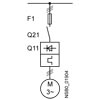
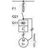
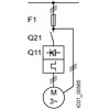
Note:
The specified short-circuit breaking capacities Iq in kA are covered by combination tests. Smaller fuses than those specified can be used at any time as smaller ones trip more quickly in the event of a short circuit (unchanged short-circuit breaking capacity) and thus protect the soft starter in any case. The dimensioning of the short-circuit components must, however, be suitable for the connected three-phase motor and the line protection for the cables used.
In inside-delta circuits, motor feeders with soft starters can only be operated in systems with up to 600 V.
Motor feeders according to IEC with 3NE1/3NB3 SITOR fuses
gR/gS class full-range fuses for semiconductor protection,
cable and line protection (gS)
Type of coordination "2",
short-circuit breaking capacity Iq = 65 kA
Note:
For general recommendations on the setup of motor feeders with soft starters, see SIRIUS 3RW soft starters → Overview → Motor feeders with soft starters.
|
|||
|---|---|---|---|
Soft starters |
gR/gS class fuse |
Line contactor (optional) |
|
for systems |
for systems |
for systems |
|
Q11 |
F1 |
Q21 |
Q21 |
Type |
Type |
Type |
Type |
|
Type of coordination "2"
|
Standard (inline) circuit |
||
3RW5513 |
3NE1815-0 |
3RT2025 |
3RT2025 |
3RW5514 |
3NE1802-0 |
3RT2026 |
3RT2027 |
3RW5515 |
3NE1817-0 |
3RT2027 |
3RT2037 |
3RW5516 |
3NE1818-0 |
3RT2035 |
3RT2037 |
3RW5517 |
3NE1820-0 |
3RT2035 |
3RT2037 |
3RW5521 |
3NE1817-0 |
3RT2027 |
3RT2037 |
3RW5524 |
3NE1021-2 |
3RT2036 |
3RT2037 |
3RW5525 |
3NE1022-0 |
3RT2037 |
3RT2046 |
3RW5526 |
3NE1224-0 |
3RT2038 |
3RT2046 |
3RW5527 |
3NE1224-0 |
3RT2046 |
3RT2047 |
3RW5534 |
3NE1225-0 |
3RT1054 |
3RT1054 |
3RW5535 |
3NE1227-0 |
3RT1055 |
3RT1055 |
3RW5536 |
3NE1230-0 |
3RT1056 |
3RT1064 |
3RW5543 |
3NE1230-21) |
3RT1064 |
3RT1064 |
3RW5544 |
3NE1331-0 |
3RT1065 |
3RT1065 |
3RW5545 |
3NE1334-2 |
3RT1075 |
3RT1075 |
3RW5546 |
3NE1334-2 |
3RT1075 |
3RT1075 |
3RW5547 |
3NE1436-2 |
3RT1076 |
3RT1276 |
3RW5548 |
3NE1437-2 |
3TF68 |
3TF68 |
3RW5552 |
3NB3350-1KK26 |
3TF68 |
3TF69 |
3RW5553 |
3NB3351-1KK26 |
3TF69 |
3TF69 |
3RW5554 |
3NB3351-1KK26 |
-- |
-- |
3RW5556 |
3NB3354-1KK26 |
-- |
-- |
3RW5558 |
3NB3357-1KK26 |
-- |
-- |
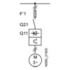
1) Only for systems up to 500 V.
Note:
The specified short-circuit breaking capacities Iq in kA are covered by combination tests. Smaller fuses than those specified can be used at any time as smaller ones trip more quickly in the event of a short circuit (unchanged short-circuit breaking capacity) and thus protect the soft starter in any case. The dimensioning of the short-circuit components must, however, be suitable for the connected three-phase motor and the line protection for the cables used.
In inside-delta circuits, a gR/gS class full-range fuse could not provide the semiconductor protection of the delta-connected soft starter with a short-circuit breaking capacity that is adequate for practical use. In this case, we recommend using aR class partial-range fuses for semiconductor protection for type of coordination "2", see next table.
Motor feeders according to IEC with 3NE8/3NE3/3NC3 fuses
aR class partial-range fuses for semiconductor protection
Type of coordination "2",
short-circuit breaking capacity Iq = 65 kA
Note:
For general recommendations on the setup of motor feeders with soft starters, see SIRIUS 3RW soft starters → Overview → Motor feeders with soft starters.
|
|
|
||||||||
|---|---|---|---|---|---|---|---|---|---|---|
Soft starters |
gG class fuse |
aR class fuse |
Line contactor (optional) |
gG class fuse |
aR class fuse |
Line contactor (optional) |
||||
for systems |
for systems |
for systems |
for systems |
for systems |
for systems |
for systems |
for systems |
for systems |
for systems |
|
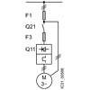
Q11 |
F1 |
F3 |
Q21 |
Q21 |
F1 |
F3 |
Q21 |
Q21 |
Q21 |
Q21 |
Type |
Type |
Type |
Type |
Type |
Type |
Type |
Type |
Type |
Type |
Type |
|
Type of coordination "2"
|
Standard (inline) circuit |
Inside-delta circuit |
||||||||
3RW5513 |
3NA3820-6 |
3NE8017-1 |
3RT2025 |
3RT2025 |
3NA3820-6 |
3NE8017-1 |
3RT2027 |
3RT2035 |
3RT2025 |
3RT2025 |
3RW5514 |
3NA3820-6 |
3NE8020-1 |
3RT2026 |
3RT2027 |
3NA3820-6 |
3NE8020-1 |
3RT2027 |
3RT2037 |
3RT2026 |
3RT2027 |
3RW5515 |
3NA3822-6 |
3NE8021-1 |
3RT2027 |
3RT2037 |
3NA3822-6 |
3NE8021-1 |
3RT2036 |
3RT2037 |
3RT2027 |
3RT2037 |
3RW5516 |
3NA3824-6 |
3NE8022-1 |
3RT2035 |
3RT2037 |
3NA3824-6 |
3NE8022-1 |
3RT2037 |
3RT2038 |
3RT2035 |
3RT2037 |
3RW5517 |
3NA3824-6 |
3NE8024-1 |
3RT2035 |
3RT2037 |
3NA3824-6 |
3NE8024-1 |
3RT2038 |
3RT2046 |
3RT2035 |
3RT2037 |
3RW5521 |
3NA3824-6 |
3NE8021-1 |
3RT2027 |
3RT2037 |
3NA3824-6 |
3NE8021-1 |
3RT2036 |
3RT2037 |
3RT2027 |
3RT2037 |
3RW5524 |
3NA3824-6 |
3NE8024-1 |
3RT2036 |
3RT2037 |
3NA3824-6 |
3NE8024-1 |
3RT2046 |
3RT2047 |
3RT2036 |
3RT2037 |
3RW5525 |
3NA3830-6 |
3NE3227 |
3RT2037 |
3RT2046 |
3NA3830-6 |
3NE3227 |
3RT2047 |
3RT1054 |
3RT2037 |
3RT2046 |
3RW5526 |
3NA3132-6 |
3NE3227 |
3RT2038 |
3RT2046 |
3NA3132-6 |
3NE3227 |
3RT1055 |
3RT1055 |
3RT2038 |
3RT2046 |
3RW5527 |
3NA3136-6 |
3NE3227 |
3RT2046 |
3RT2047 |
3NA3136-6 |
3NE3227 |
3RT1056 |
3RT1056 |
3RT2046 |
3RT2047 |
3RW5534 |
3NA3244-6 |
3NE3231 |
3RT1054 |
3RT1054 |
3NA3244-6 |
3NE3231 |
3RT1064 |
3RT1064 |
3RT1054 |
3RT1054 |
3RW5535 |
3NA3244-6 |
3NE3233 |
3RT1055 |
3RT1055 |
3NA3244-6 |
3NE3233 |
3RT1065 |
3RT1065 |
3RT1055 |
3RT1055 |
3RW5536 |
3NA3365-6 |
3NE3334-0B |
3RT1056 |
3RT1064 |
3NA3365-6 |
3NE3334-0B |
3RT1066 |
3RT1075 |
3RT1056 |
3RT1064 |
3RW5543 |
2 x 3NA3354-6 |
3NE3333 |
3RT1064 |
3RT1064 |
2 x 3NA3354-6 |
3NE3333 |
3RT1075 |
3RT1075 |
3RT1064 |
3RT1064 |
3RW5544 |
2 x 3NA3354-6 |
3NE3335 |
3RT1065 |
3RT1065 |
2 x 3NA3354-6 |
3NE3335 |
3RT1076 |
3RT1076 |
3RT1065 |
3RT1065 |
3RW5545 |
2 x 3NA3365-6 |
3NE3336 |
3RT1075 |
3RT1075 |
2 x 3NA3365-6 |
3NE3336 |
3TF68 |
3TF68 |
3RT1075 |
3RT1075 |
3RW5546 |
2 x 3NA3365-6 |
3NE3340-8 |
3RT1075 |
3RT1075 |
2 x 3NA3365-6 |
3NE3340-8 |
3TF69 |
3TF69 |
3RT1075 |
3RT1075 |
3RW5547 |
2 x 3NA3365-6 |
3NE3340-8 |
3RT1076 |
3RT1276 |
2 x 3NA3365-6 |
3NE3340-8 |
3TF69 |
3TF69 |
3RT1076 |
3RT1276 |
3RW5548 |
2 x 3NA3365-6 |
3NC3342-1U |
3TF68 |
3TF68 |
2 x 3NA3365-6 |
3NC3342-1U |
-- |
-- |
3TF68 |
3TF68 |
3RW5552 |
2 x 3NA3365-6 |
3NC3343-1U |
3TF68 |
3TF69 |
-- |
3NC3343-1U |
-- |
-- |
3TF68 |
3TF69 |
3RW5553 |
2 x 3NA3365-6 |
3NC3343-1U |
3TF69 |
3TF69 |
-- |
3NC3343-1U |
-- |
-- |
3TF69 |
3TF69 |
3RW5554 |
2 x 3NA3365-6 |
3NC3343-1U |
-- |
-- |
-- |
3NC3343-1U |
-- |
-- |
-- |
-- |
3RW5556 |
3 x 3NA3365-6 |
3 x 3NE3340-8 |
-- |
-- |
-- |
3 x 3NE3340-8 |
-- |
-- |
-- |
-- |
3RW5558 |
3 x 3NA3365-6 |
3 x 3NE3340-8 |
-- |
-- |
-- |
3 x 3NE3340-8 |
-- |
-- |
-- |
-- |
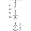
Note:
The specified short-circuit breaking capacities Iq in kA are covered by combination tests. Smaller fuses than those specified can be used at any time as smaller ones trip more quickly in the event of a short circuit (unchanged short-circuit breaking capacity) and thus protect the soft starter in any case. The dimensioning of the short-circuit components must, however, be suitable for the connected three-phase motor and the line protection for the cables used.
For CLASS 10 applications, as an alternative to the gG class full-range fuses for cable and line protection 3NA3 (F1), 3RV2 motor starter protectors or 3VA circuit breakers can also be used, possibly with reduced short-circuit breaking capacity, see Table "Motor feeders according to IEC with 3RV2 motor starter protectors or 3VA circuit breakers (without semiconductor protection)". In these cases, optional line contactors can be dispensed with.
In inside-delta circuits, motor feeders with soft starters can only be operated in systems with up to 600 V.
Reversing operation with reversing contactors
Note:
For general recommendations on the setup of motor feeders with soft starters, see SIRIUS 3RW soft starters → Overview → Motor feeders with soft starters.
(For an example circuit, see
3RW55 Equipment Manual, Appendix A.3)
Soft starters |
Reversing contactor assembly |
Reversing contactor |
||
|---|---|---|---|---|
for systems up to 480 V |
for systems up to 690 V |
for systems up to 480 V |
for systems up to 690 V |
|
Q11 |
Q21/Q22 |
Q21/Q22 |
Q21/Q22 |
Q21/Q22 |
Type |
Type |
Type |
Type |
Type |
3RW5513 |
3RA2325 |
3RA2325 |
3RT2025 |
3RT2025 |
3RW5514 |
3RA2326 |
3RA2327 |
3RT2026 |
3RT2027 |
3RW5515 |
3RA2327 |
3RA2337 |
3RT2027 |
3RT2037 |
3RW5516 |
3RA2335 |
3RA2337 |
3RT2035 |
3RT2037 |
3RW5517 |
3RA2335 |
3RA2337 |
3RT2035 |
3RT2037 |
3RW5521 |
3RA2327 |
3RA2337 |
3RT2027 |
3RT2037 |
3RW5524 |
3RA2336 |
3RA2337 |
3RT2036 |
3RT2037 |
3RW5525 |
3RA2337 |
3RA2346 |
3RT2037 |
3RT2046 |
3RW5526 |
3RA2338 |
3RA2346 |
3RT2038 |
3RT2046 |
3RW5527 |
3RA2346 |
3RA2347 |
3RT2046 |
3RT2047 |
3RW5534 |
-- |
-- |
3RT1054 |
3RT1054 |
3RW5535 |
-- |
-- |
3RT1055 |
3RT1055 |
3RW5536 |
-- |
-- |
3RT1056 |
3RT1064 |
3RW5543 |
-- |
-- |
3RT1064 |
3RT1064 |
3RW5544 |
-- |
-- |
3RT1065 |
3RT1065 |
3RW5545 |
-- |
-- |
3RT1075 |
3RT1075 |
3RW5546 |
-- |
-- |
3RT1075 |
3RT1075 |
3RW5547 |
-- |
-- |
3RT1076 |
3RT1276 |
3RW5548 |
-- |
-- |
3TF68 |
3TF68 |
3RW5552 |
-- |
-- |
3TF68 |
3TF69 |
3RW5553 |
-- |
-- |
3TF69 |
3TF69 |
3RW5554 |
-- |
-- |
-- |
-- |
3RW5556 |
-- |
-- |
-- |
-- |
3RW5558 |
-- |
-- |
-- |
-- |
DC braking with braking contactors
Note:
For general recommendations on the setup of motor feeders with soft starters, see SIRIUS 3RW soft starters → Overview → Motor feeders with soft starters.
(For an example circuit, see
3RW55 Equipment Manual, Appendix A.3)
Soft starters |
DC braking contactor |
DC braking contactor assembly |
|||
|---|---|---|---|---|---|
for systems up to 400 V |
for systems up to 480 V |
for systems up to 690 V |
|||
with 2 NC contacts + 2 NO contacts |
with 3 NO contacts |
with 3 NO contacts |
with 3 NO contacts |
with 3 NO contacts |
|
Q11 |
Q93 |
Q91 |
Q92 |
Q91 |
Q92 |
Type |
Type |
Type |
Type |
Type |
Type |
3RW5513 |
3RT2517 |
3RT2015 |
3RT2016 |
3RT2015 |
3RT2016 |
3RW5514 |
3RT2518 |
3RT2015 |
3RT2017 |
3RT2015 |
3RT2023 |
3RW5515 |
3RT2526 |
3RT2015 |
3RT2025 |
3RT2015 |
3RT2025 |
3RW5516 |
3RT2526 |
3RT2015 |
3RT2025 |
3RT2015 |
3RT2027 |
3RW5517 |
3RT2535 |
3RT2015 |
3RT2027 |
3RT2015 |
3RT2027 |
3RW5521 |
3RT2526 |
3RT2015 |
3RT2025 |
3RT2015 |
3RT2025 |
3RW5524 |
3RT2535 |
3RT2016 |
3RT2027 |
3RT2016 |
3RT2035 |
3RW5525 |
-- |
3RT2024 |
3RT2027 |
3RT2024 |
3RT2037 |
3RW5526 |
-- |
3RT2025 |
3RT2035 |
3RT2025 |
3RT2037 |
3RW5527 |
-- |
3RT2027 |
3RT2036 |
3RT2027 |
3RT2037 |
3RW5534 |
-- |
3RT2035 |
3RT2037 |
3RT2035 |
3RT2038 |
3RW5535 |
-- |
3RT2036 |
3RT2038 |
3RT2036 |
3RT2046 |
3RW5536 |
-- |
3RT2037 |
3RT2046 |
3RT2037 |
3RT2047 |
3RW5543 |
-- |
3RT2045 |
3RT2047 |
3RT2045 |
3RT1054 |
3RW5544 |
-- |
3RT2045 |
3RT1055 |
3RT2045 |
3RT1055 |
3RW5545 |
-- |
3RT2446 |
3RT1056 |
3RT2046 |
3RT1056 |
3RW5546 |
-- |
3RT1055 |
3RT1056 |
3RT1055 |
3RT1064 |
3RW5547 |
-- |
3RT1456 |
3RT1065 |
3RT1456 |
3RT1065 |
3RW5548 |
-- |
3RT1456 |
3RT1066 |
3RT1456 |
3RT1075 |
3RW5552 |
-- |
3RT1065 |
3RT1075 |
3RT1065 |
3RT1075 |
3RW5553 |
-- |
3RT1065 |
3RT1075 |
3RT1065 |
3RT1075 |
3RW5554 |
-- |
3RT1466 |
3RT1076 |
3RT1466 |
3RT1076 |
3RW5556 |
-- |
3RT1476 |
3TF68 |
3RT1476 |
3TF68 |
3RW5558 |
-- |
3RT1476 |
3TF69 |
3RT1476 |
3TF69 |
Article number |
3RW551.-.HA.4 |
3RW551.-.HA.5 |
3RW552.-.HA.4 |
3RW552.-.HA.6 |
3RW554.-.HA.4 |
3RW554.-.HA.6 |
3RW555.-.HA.4 |
3RW555.-.HA.6 |
||
|---|---|---|---|---|---|---|---|---|---|---|
Installation/ mounting/ dimensions |
||||||||||
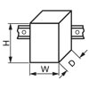
Width x Height x Depth |
mm |
170 × 275 × 152 |
185 × 306 × 203 |
210 × 393 × 203 |
478 × 764 × 241 |
|||||
fastening method |
screw fixing |
|||||||||
mounting position |
Vertical (can be rotated +/- 90° and tilted forward or backward +/- 22.5°) |
|||||||||
required spacing with side-by-side mounting |
||||||||||
|
mm |
100 |
||||||||
|
mm |
5 |
||||||||
|
mm |
75 |
||||||||
installation altitude at height above sea level maximum 1) |
m |
5 000 |
2 000 |
5 000 |
2 000 |
5 000 |
2 000 |
|||
protection class IP on the front according to IEC 60529 |
IP20; -- |
IP00; IP20 with cover |
IP00; -- |
|||||||
touch protection on the front according to IEC 60529 |
finger-safe, for vertical contact from the front |
finger-safe, for vertical contact from the front with cover |
-- |
|||||||
Ambient conditions |
||||||||||
ambient temperature |
||||||||||
|
°C |
-25 ... +60 |
||||||||
|
°C |
-40 ... +80 |
-25 ... +80 |
-40 ... +80 |
||||||
environmental category according to IEC 60721 |
||||||||||
|
3K6 (no ice formation, only occasional condensation), 3C3 (no salt mist), 3S2 (sand must not get into the devices), 3M6 |
|||||||||
|
1K6 (only occasional condensation), 1C2 (no salt mist), 1S2 (sand must not get inside the devices), 1M4 |
|||||||||
|
2K2, 2C1, 2S1, 2M2 (max. fall height 0.3 m) |
|||||||||
| 1) Derating as of 1000 m, see catalog |
| 2) Please observe derating at temperatures of 40 °C or above |
Article number |
3RW55..-.HA0. |
3RW55..-.HA1. |
||
|---|---|---|---|---|
Control circuit/ Control |
||||
control supply voltage |
||||
|
V |
24/24 |
--/-- |
|
|
-- |
110 ... 250 |
||
Relative negative tolerance/Relative positive tolerance at AC |
% |
-20/20 |
-15/10 |
|
Relative negative tolerance/Relative positive tolerance at DC |
% |
-20/20 |
--/-- |
|
control supply voltage frequency |
Hz |
50 ... 60 |
||
|
-10/10 |
|||
design of the overvoltage protection |
Varistor |
|||
design of short-circuit protection for control circuit 1) |
4 A gG fuse (Icu=1 kA), 6 A quick-acting fuse (Icu=1 kA), C1 miniature circuit breaker (Icu= 600 A), C6 miniature circuit breaker (Icu= 300 A) |
|||
| 1) Is not part of scope of supply |
Article number |
3RW551.-.HA.4 |
3RW552.-.HA.4 |
3RW551.-.HA.5 |
3RW552.-.HA.6 |
||
|---|---|---|---|---|---|---|
Power Electronics |
||||||
operating voltage |
V |
200 ... 480 |
200 ... 600 |
200 ... 690 |
||
|
% |
-15/10 |
||||
operating voltage at inside-delta circuit |
V |
200 ... 480 |
200 ... 600 |
|||
|
% |
-15/10 |
||||
Operating frequency |
Hz |
50 ... 60 |
||||
|
% |
-10/10 |
||||
blocking voltage of the thyristor maximum |
V |
1 600 |
1 400 |
1 600 |
1 800 |
|
minimum load [%] 1) |
% |
10 |
||||
wire length between soft starter and motor maximum |
m |
800 |
||||
| 1) Relative to set Ie |